www.selbit.pl
- 7 -
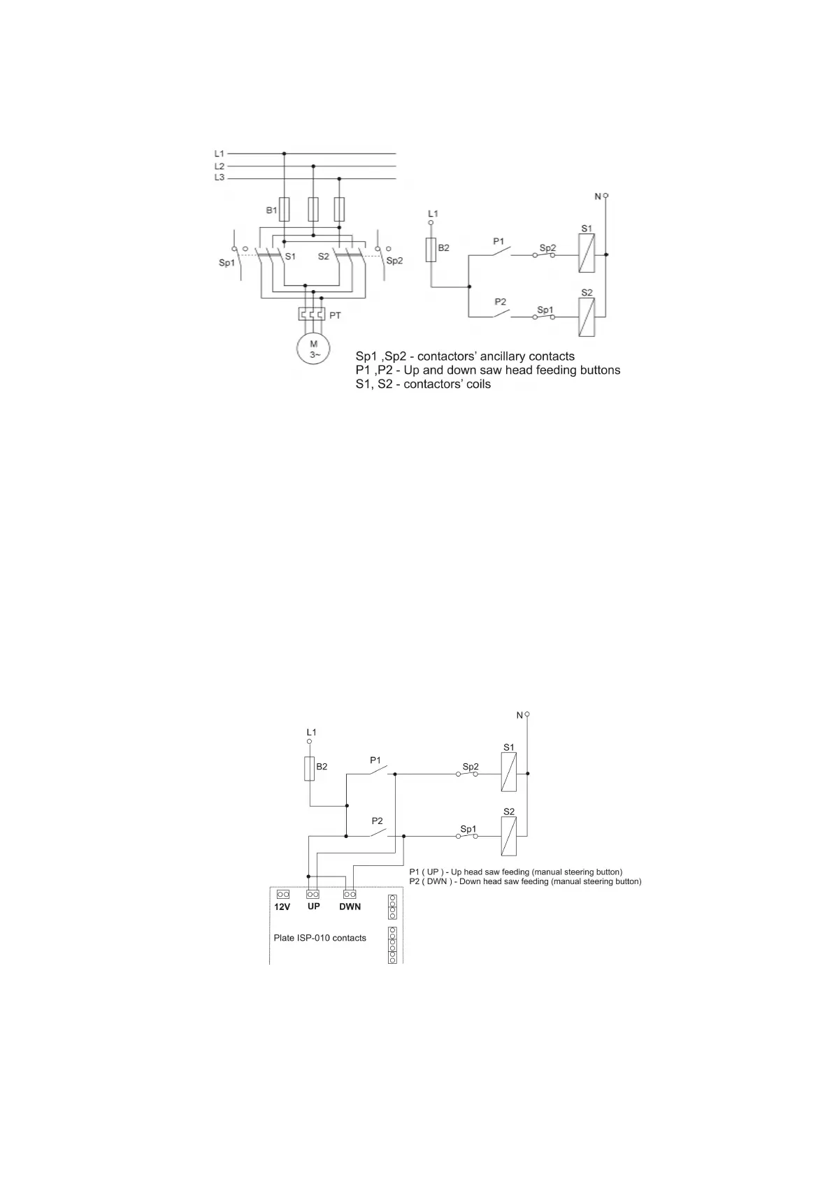
Fig. 6 Contactors and ancillary contacts connection diagram.
Contactors steering cables connection
Head saw up and down feeding buttons which sawing frame machines contains
should be without holding shot-circuit type (that cause of their contact only while pressing,
when there is no press they should be disconnected). Please connect above buttons using cable
which contains two pairs of wires in doubled round insulation with proper diameter to lead
them through bigger of the hole in the back casing of the controller. One pair of the wires
please connect in parallel with up head saw feeding button (fig. 7 ) and the second one with
down head saw feeding button. Please use special clip or tined the tips of the wires. Please use
also different wire colors which helps you in easy identification during connection with the
controller’s electronics main plate. Place the cable as far as it is possible from other wires and
lead them in the place of controller’s mounting.
Fig. 7 Contactors steering cables diagram connections
There is a possibility to connect contactors steering cables direct to the contactors thus
to meet original connection configurations but instructions given above provide simpler
solution.