Description of keys
* Encoder E1:
selection of parameter 1 or 2.
* Key K1: access to the quick menu (WF 110/111) (with coil
compartment closed) or cooling unit test (WF 110) (with coil
compartment open and in MIG operating mode).
quick menu
cooling unit test (WF110)
* Key K2: selection of MIG short, MIG pulsed (WF 110), MMA,
ARC-AIR, TIG LIFT welding procedure; the change is possible
only with the arc switched off. The arc-air procedure is possi-
ble only with PSR 352 and 503 or PSM 408, PSM 508 and
PSM 708.
MIG Short/Spray MIG Pulsed (WF 110)
MMA ARC-AIR
TIG Lift
* Key K3: in MIG procedure and with coil compartment closed,
selects the torch button functions or wire feed functions when
the key is kept pressed (with coil compartment open).
2 stage 4 stage
crater-filler spot welding
spot-pause
With coil compartment open, it takes on the wire feed function.
* Key K4: in MIG procedure it has a gas test function.
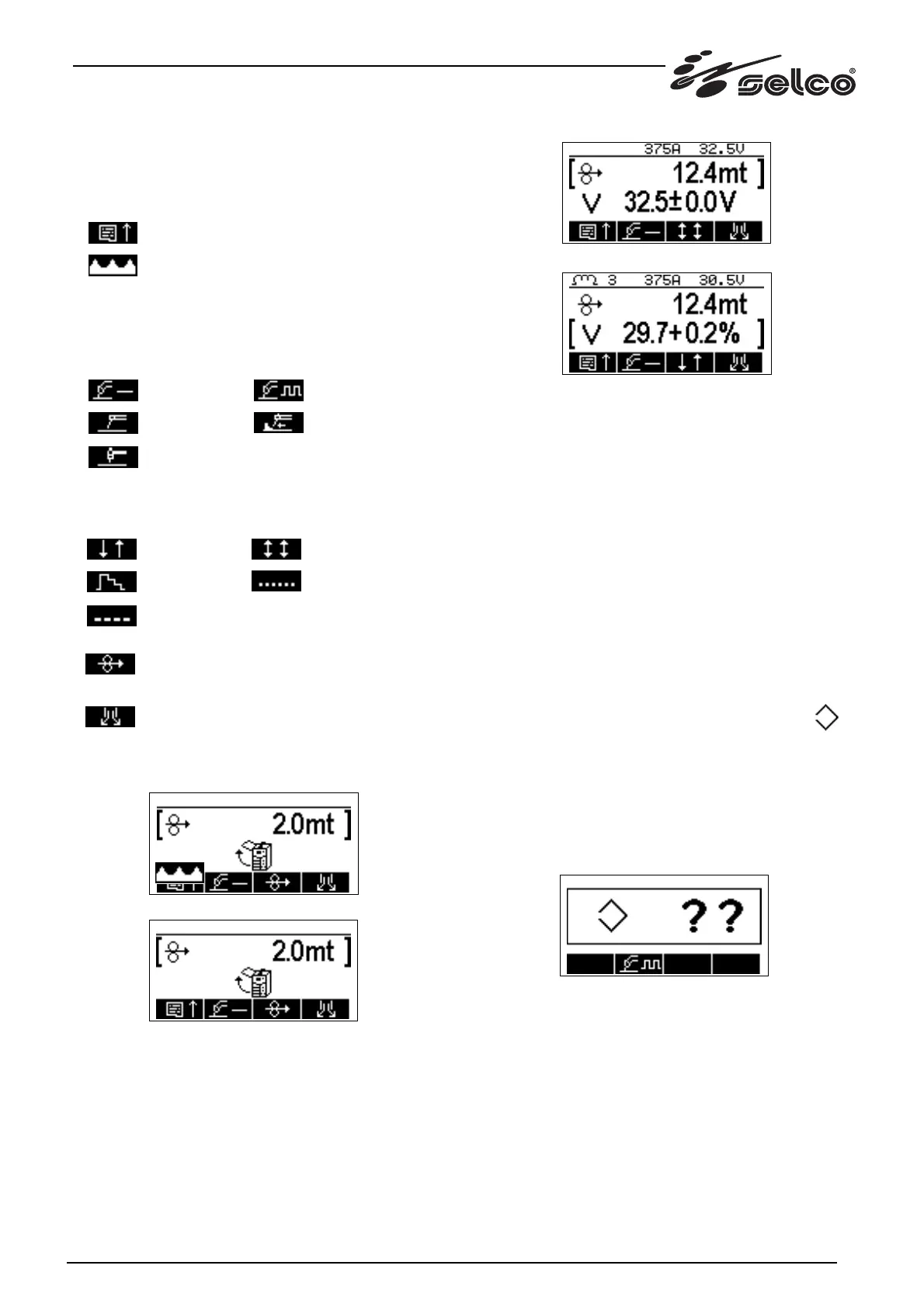
If the coil compartment is open in MIG mode, the screen that
appears on display D1 will be modified as follows:
(WF 110)
(WF 111)
When key K3 is pressed, it permits wire feed, while the two main
parameters are replaced by one single parameter for modifica-
tion of the speed. With the door open, welding and wire feed
with the torch button are disabled; the wire speed can be set
from 1.0 to 22.0 m/min and if it is beyond the synergy limits
when the door is closed again, it is brought back to within the
permitted minimum or maximum. With the door open the hea-
ding of the first line is also removed.
During the welding phase display D1 is modified as follows:
(WF 110)
(WF 111)
As can be seen, instead of the type of material, the welding cur-
rent and voltage values are displayed in the heading. The mea-
surements are shown for the last procedure where welding has
been performed: in the other cases 0 or the heading of the mate-
rial is displayed. The measurements disappear in MIG if the
Program parameter is selected; the measurements disappear
permanently if the Program parameter is changed.
In MIG the value of the recommended inductance is also displa-
yed on the left (WF 111).
The measurements and the fixed inductance no. 3 (WF 111) are
always displayed in MMA, TIG and ARC-AIR.
1.3.2 Selection of synergic curve in MIG procedure
A fundamental parameter in MIG is the parameter that permits
selection of the synergic curves: it is associated with a number that
ranges from 0 (=Off) to 60 (WF 110) and 0 (=Off) to 31 (WF 111).
The parameter is displayed with the following symbol:
Off corresponds to the manual program for use of the machine out-
side the synergic curves and nothing is displayed in the heading.
For the other programs each number corresponds to a synergic
curve relating to a particular metal-wire diameter-gas which is
displayed in the heading.
If a program number is selected for which the synergic curve is
not available (e.g. MIG Pulsed with gas CO2) a question will
appear on display D1 as shown in the following screen (WF 110).
By rotating the encoder, the user can choose a new program
valid for MIG Pulsed and then confirm by pressing the Encoder
key, or leave the program unchanged and switch to MMA by
pressing key K2.
For WF110: the Synergic Program Number parameter is the only
one in common between the MIG Short and Pulsed welding pro-
cedures: all the other parameters present in both the procedures
can have different values which are modified and stored inde-
pendently.
23