32
2.0 DESCRIPTION OF THE APPARATUS
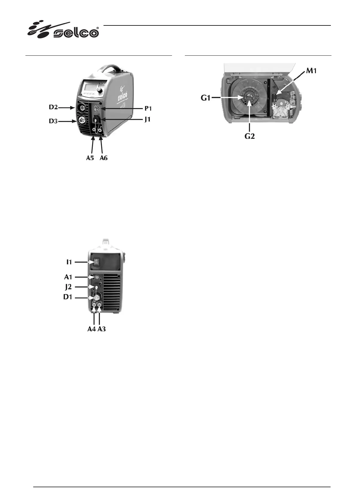
Fig. 2 Front control panel
* J1: remote control connector (optional).
* P1: gas flow regulation knob.
* D2: the MMA torch must be connected to this socket.
* D3: the MIG torch must be connected to this socket.
* A5: the delivery tube of the MIG torch (usually blue) is con-
nected here.
* A6: the return tube of the MIG torch (usually red) is connec-
ted here.
Fig. 3 Rear control panel
* I1: on-off switch. With the switch off, the Genesis 352 PSR
and Genesis 503 PSR welding systems are in stand-by.
* A1: gas fitting.
* J2: this is coupled to the multi-pole connector of the cable
bundle coming from the generator.
* D1: to this socket is connected the power cable of the cable
bundle coming from the generator.
* A4: the pipe bundle return pipe must be connected (red).
* A3: the pipe bundle delivery pipe must be connected (blue).
3.0 INSTALLATION
Fig. 4 Details of the trolley
a) Connect the cable bundle to the socket D1 / J2 (fig. 3) and the
pipes of the cooling liquid, if used, to the sockets A3 / A4.
b) Connect the gas pipe to the rear fitting (fig.3).
c) Open the trolley mobile bonnet, exerting pressure on the two
slide fastenings, and remove any accessory elements provid-
ed in the compartment.
d) Check that the roller groove coincides with the diameter of
the wire you wish to use.
e) Unscrew the ring nut (G1 fig.4) from the coil reel and insert
the coil.
Fit the reel metal pin into its housing, replace the ring nut (G1)
and adjust the friction screw (G2 fig.4).
f) Release the feed support of the gearmotor (M1 fig.4), sliding
the end of the wire into the wire guide bush and, passing it
over the roller, into the torch fitting.
Lock the feed support (M1) in position, checking that the wire
has entered the roller groove.
g) Insert the torch, complete with sheath, into the central fitting
(D3 fig.2), fully tightening the ring nut. If the torch is water-
cooled, connect the delivery and return pipes to the cou-
plings (A5 / A6 fig.2).
If the cable bundle cooling liquid hoses are connected and the
torch is not cooled by water, perform a by-pass with one hose
and two quick-fit couplings on the fittings (A5 / A6 fig. 2) and
check that they are well secured.
Switch the power source on only after checking correct tight-
ening of connectors and quick-fit couplings.