User ManualUser Manual
Chapter 6
67
66
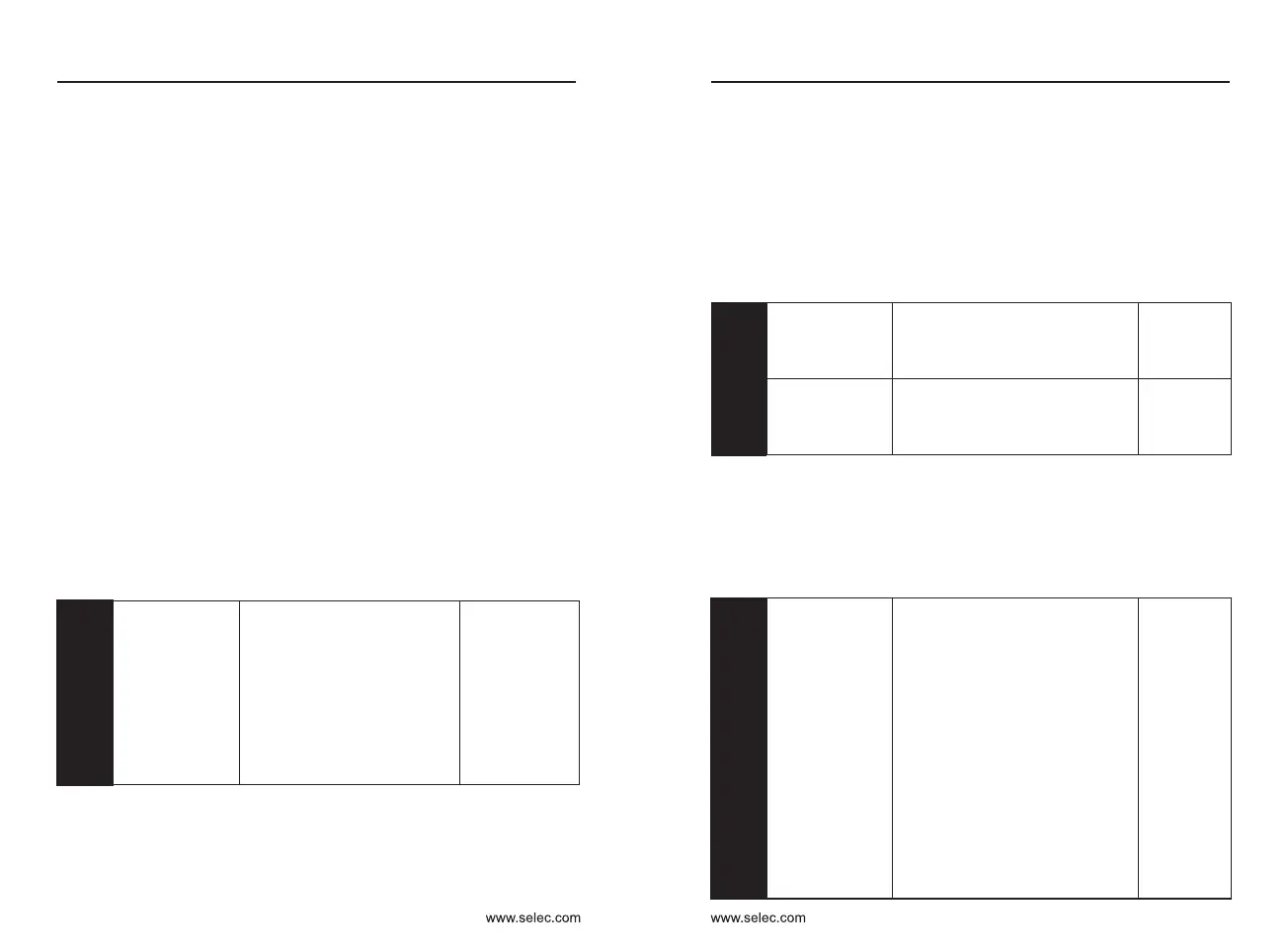
110~150%
Inverter in the running process, detect the bus voltage is higher than that of PA
- 17 set value corresponding to the rated voltage (100%), open the dc brake.
This function should be used together with brake unit and brake resistance,
otherwise it is invalid.
DC braking factor
Default: 30
PA-17
Depending on model
Dead zone compensation time on different models are different.
Dead zone
compensation time
Default: Depending
on model
PA-21
100~300%
Frequency converter in the process of running current is higher than the set
value, the inverter frequency reduction.100% of the rated current of the
converter
Reduce the frequency
current point
Default: 210
PA-22
7-1 Malfunction and Solutions
FAULT CORRECTING
Fault
indication
Code
Fault type
Fault cause
Solutions
LU
3
Under
voltage
Abnormal power
supply or loose
contact
Input voltage and
wiring should be
checked
OU
4
Over
voltage
1. Input voltage
2. Rapid deceleration
3. Excessive inertia
load
1. Check input voltage
2. Increase deceleration
time
3. Select dynamic
braking components
OC
6
Over
current
1. Mismatch of
capacity
2. Low voltage of grid
3. Rapid acceleration
and deceleration
4. High torque of
inertia load
5. Abnormal load
1. Select converter with
large capacity
2. Check power source
and wiring
3. Increase Acc-Dec
time
4. Select applicable
braking parts
5. Detect and reduce
load changing
OL
5
Overload
(Converter)
1. Please refer to fault
cause of over current
(OC)
2. Overload (motor)
3. Inapplicable setting
of V/F curve
1. Please refer to
solutions for over
current(OC)
2. Reduce motor load
3. Reset parameters
OL1
15
Overload
(Motor)
1. Low voltage of grid
2. Excessive motor
stalling or load
changing
3. Inapplicable setting
of V/F curve, rated
current or critical
point of overload
protection
1. check the voltage of
grid
2. check motor load
3. reset parameters
6 : Multi-segment command, the main frequency can be composed of four
multi-segment terminals with different state combinations corresponding
to 16 kinds of set frequency values.
Control board J2 jumper selects whether AI2 is voltage input U or current
input I (20mA corresponds to 10V).The input voltage value of AI1 and AI2
and the corresponding relationship with the target frequency can be set by
P4-13~27.
5 : The main frequency is given by the terminal pulse signal. The pulse signal
specifications are: voltage range 9V ~ 30V, frequency range 0 ~ 100 kHz.
The pulse signal can only be input from terminal X6. (See P4-28~P4-31)
4 : Panel potentiometer setting, the main frequency is set by the panel
potentiometer.
3 : Analog AI2 setting, the main frequency is determined by AI2 input 0V ~
10V or 4mA ~ 20mA
Set PC group function code corresponding to 16 multi-segment
instructions, multi-segment command terminal function is set in P4 group
7 : The simple PLC main frequency is given by the PLC, and the PLC running
frequency and running time are set in the PC group.
8 : PID, the main frequency is given by the output controlled by the process
PID. Generally used for closed-loop control in the field, such as constant
pressure closed-loop control, constant tension closed-loop control, etc., it
is necessary to set the PA group PID function parameters.
9 : Communication given (optional), the main frequency is given by the host
computer through communication.
P0-04
Auxiliary
frequency
source Y selection
Default:0
0: Digital setting (non-retentive
at power failure)
1: Digital setting (retentive at
power failure)
2: AI1 3: AI2
4: panel potentiometer
5: Pulse setting (X6)
6:Multi-segment instruction
7: Simple PLC 8: PID
9: Communication given
When the auxiliary frequency source Y is used as an independent
frequency reference channel (X to Y switching), its usage is the same as that
of the main frequency source X P0-03. Note when the auxiliary frequency
source is used as the superimposed reference (the composite frequency of
the main frequency source X and the auxiliary source Y is given) :
1 : When the auxiliary frequency source Y is digitally given, P0-08 does not
work. The user adjusts the frequency based on the ▲, ▼ keys of the
keyboard or the UP and DOWN of the terminal directly on the basis of the
main given frequency.
2 : When the auxiliary frequency source is analog input AI1, AI2 or pulse input
timing, the frequency range is set by P0-05 and P0-06.
3 : The selection of auxiliary frequency source Y and main frequency source
X cannot be set to the same channel, that is, P0-03 and P0-04 should not
be set to the same value, otherwise it will cause confusion.
Default: 0
P0-05
0: relative to the maximum
frequency
1: relative to the frequency
source X
Auxiliary source
Y range selection
when
superimposing
P0-06
Auxiliary
frequency source
Y range when
superimposed
Default: 100%
0%~150%
When the frequency source is selected as frequency superposition (P0-
07 is set to 1, 3 or 4), it is used to determine the adjustment range of the
auxiliary frequency source.
Note: If P0-05 is selected to be relative to the main frequency source X,
the range of the auxiliary frequency source will change as the main frequency
X changes.
Default: 00
P0-07
Ones place: frequency source
selection
0: main frequency source X
1: X and Y operation (operation
relationship determined by Tens
position)
2: Switchover between X and Y
3: Switchover between X and
"X and Y operation"
4: Switchover between Y and
"X and Y operation"
Tens place: frequency source
primary and secondary operation
relationship
0: main + auxiliary
1: main - auxiliary
2: the maximum of the two
3: the minimum of the two
Frequency
source
overlay selection
Chapter 6

 Loading...