User Manual
154
User Manual
155
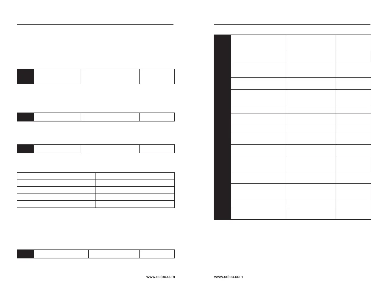
A5-07
SVC optimization
mode selection
0: Not optimized
1: Optimized mode 1
2: Optimized mode 2
Default:2
ptimization Mode 2: Use when there is a requirement for higher speed
stability.
Optimization Mode 1: Used when there is a higher torque control linearity
requirement.
A5-08
Dead time adjustment
100%〜200%
Default:150%
Set for 1140V voltage level. Adjusting this value can improve the effective
voltage usage. If the adjustment is too small, the system may be unstable.
User modification is not recommended
A5-09
Overvoltage setting
200.0V 〜 2200.0V
Default:depend
Used to set the voltage value of the inverter overvoltage fault. The
different voltage levels are respectively:
Voltage Level
Overpressure point Default
Single phase 220V
400.0V
Three phase 220V
400.0V
Three phase 380V
810.0V
Three phase 480V
890.0V
Default is also the upper limit of the internal overvoltage protection of the
inverter. This parameter setting takes effect only when the A5-09 setting
value is less than the respective voltage level Default. Above Default, the
Default is the standard.
A6 Group : AI curve setting
A6-00
AI curve 4 minimum input
-10.00V 〜 A6-02
Default:0.00V
AI curve 4 minimum
input correspondence
setting
-100.0% 〜 +100.0%
Default:0.0%
AI curve 4 inflection
point 1 input
A6-00 〜 A6-04
Default:3.00V
AI curve 4 inflection
point 1 input
corresponding setting
-100.0% 〜 +100.0%
Default:30%
AI curve 4 inflection
point 2 input
A6-02 〜 A6-06
Default:6.00V
AI curve 4 inflection
point 2 input
corresponding setting
-100.0% 〜 +100.0%
Default:60%
AI curve 4 maximum input
A6-06 〜 +10.00V
Default:10.00V
AI curve 4 maximum
input corresponding setting
-100.0% 〜 +100.0%
Default:100%
AI curve 5 minimum input
-10.00V 〜 A6-10
Default:-10.00V
AI curve 5 minimum
input corresponding setting
-100.0% 〜 +100.0%
Default : -100.0%
AI curve 5 inflection
point 1 input
A6-08 〜 A6-12
Default: -3.00V
AI curve 5 inflection
point 1 input
corresponding setting
-100.0% 〜 +100.0%
Default: -30.0%
AI curve 5 inflection
point 2 input
A6-10 〜 A6-14
Default:3.00V
AI curve 5 inflection
point 2 input
corresponding setting
-100.0% 〜 +100.0%
Default:30.0%
AI curve 5 maximum input
A6-12 〜 +10.00V
Default:10.00V
AI curve 5 maximum
input corresponding setting
-100.0% 〜 +100.0%
Default:100.0%
A6-01
A6-02
A6-03
A6-04
A6-05
A6-06
A6-07
A6-08
A6-09
A6-10
A6-11
A6-12
A6-13
A6-14
A6-15
The functions of curves 4 and 5 are similar to those of curve 1 curve 3, but
curve 1 is a straight line, while curve 4 and curve 5 are 4-point curves, which
allows for a more flexible correspondence. The figure below is a schematic
diagram of curve 4 curve 5. 4
Chapter 6 Chapter 6
Single phase / three phase 220V: 200V Three phase 415V:350V
Three phase 480V:450V Three phase 690V:650V
It is used to set the voltage value of the inverter under voltage fault Err09.
The inverter with different voltage levels is 100.0%, corresponding to
different voltage points:

 Loading...