User Manual
144
User Manual
145
The amplitude of the kick frequency is the percentage of the frequency of
the kick frequency relative to the swing when the swing frequency is running,
that is, the burst frequency = swing AW × kick frequency amplitude PB-02. If
the swing is selected relative to the center frequency (PB-00 = 0), the burst
frequency is the change value. If the swing is selected relative to the
Maximum frequency (PB-00 = 1), the burst frequency is a fixed value.
The swing frequency is limited by the upper and lower frequencies.
When the swing is set relative to the center frequency (PB-00 = 0), the
swing AW = frequency source P0-07 × swing amplitude PB-01. When setting
the swing relative to the Maximum frequency (PB-00 = 1), the swing AW =
Maximum frequency P0 - 10 × swing amplitude PB-01.
This parameter is used to determine the value of the swing value and the
kick frequency.
PB-03
Wobble cycle
0.1s〜3000.0s
Default:10.0s
Swing frequency
triangle wave rise time
0.1%〜100.0%
Default:50.0%
PB-04
Wobble cycle: The time value of a complete wobble cycle.
The triangular wave rise time coefficient PB-04 is the time percentage of
the triangular wave rise time relative to the swing frequency period PB-03.
Triangle wave rise time = swing frequency period PB-03 × triangle wave rise
time coefficient PB-04, in seconds. Triangle wave fall time = swing frequency
period PB-03 × (1 - triangular wave rise time coefficient PB-04), in seconds.
PB-05
Set length
0m〜65535m
Default:1000m
Actual length
0m〜65535m
Default:0m
Pulse number per meter
0.1〜6553.5
Default:100.0
PB-06
PB-07
The above function code is used for fixed length control.
The length information is collected by the multi-function input terminal,
and the number of pulses sampled by the terminal is divided by the number of
pulses per meter PB-07, and the actual length PB-06 can be calculated.
When the actual length is greater than the set length PB-05, the output length
reaches the ON signal.
During the fixed length control, the length reset operation can be
performed through the input terminal (28).In the application, the
corresponding input terminal function needs to be set to “length count input”
(27). When the pulse frequency is high, the X6 port must be used.
PB-08
Set count value
1〜65535
Default:1000
PB-09
Specified count value
1〜65535
Default:1000
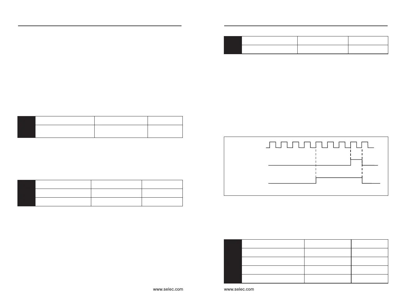
When the count value reaches the set count value PB-08, the multi-
function digital output "sets the count value reached" ON signal, and then the
counter stops counting.
The specified count value PB-09 should not be greater than the set count
value PB-08. Figure 6-32 is a schematic diagram of setting the arrival of the
count value and the arrival of the specified count value.
When the count value reaches the specified count value PB-09, the multi-
function digital output "specified count value reaches" ON signal, at which
time the counter continues to count until the "set count value" is stopped.
The count value needs to be collected through the multi-function digital
input terminal. In the application, the corresponding input terminal function
needs to be set to “counter input” (function 25). When the pulse frequency is
high, the X6 port must be used.
Figure 6-32 Setting the count value given and the specified count value
PC: Multi-segment instruction and simple PLC function
The multi-stage command of the inverter has more functions than the
normal multi-speed. In addition to the multi-speed function, it can also be
used as a voltage source for VF separation and a given source for the
process PID. To this end, the dimensions of the multi-segment instructions
are relative values.
Multi-segment instruction 0
Default:0.0
Multi-segment instruction 1
Default:0.0
Multi-segment instruction 2
Default:0.0
Multi-segment instruction 3
Default:0.0
Multi-segment instruction 4
Default:0.0
PC-00
PC-01
PC-02
PC-03
PC-04
Counting pulse
Set count
Specified count
amount relay
1 2 3 4
5
6
7
8 9
Chapter 6 Chapter 6
0.0Hz ~ ±P0-10
0.0Hz ~ ±P0-10
0.0Hz ~ ±P0-10
0.0Hz ~ ±P0-10
0.0Hz ~ ±P0-10

 Loading...