User Manual
106
User Manual
107
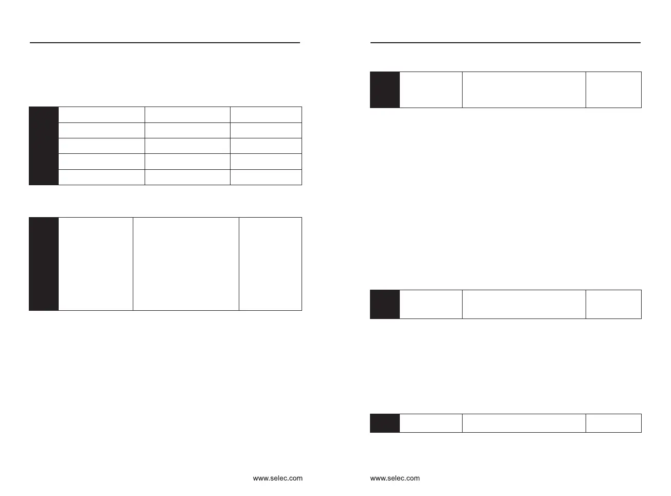
Y2 output delay time
0.0s〜3600.0s
Default:0.0s
Relay output delay time
0.0s〜3600.0s
Default:0.0s
Relay 2 delay time
0.0s〜3600.0s
Default:0.0s
Y1 output delay time
0.0s〜3600.0s
Default:0.0s
Y3 delay time (extended)
0.0s〜3600.0s
Default:0.0s
P5-18
P5-19
P5-20
P5-21
P5-17
Set the delay time of the output terminal from the state change to the
actual output change
Ones place:Y2
Tens place: Relay
Hundreds place: Relay 2
Thousands place: Y1
Ten thousand: Y3
0: The output terminal is
connected to COM and the
disconnection is invalid.
1: The output terminal is not
connected to COM, and the
disconnection is valid.
P5-22
Output terminal
valid mode selection
Default:00000
Define the valid state selection for the multi-function output terminal.
1 : Inverse logic, the digital output terminal and the corresponding common
terminal are connected to an inactive state, and the disconnection is in an
active state.
0 : Positive logic, the digital output terminal and the corresponding common
terminal are connected to the active state, and the disconnection is in the
invalid state.
P6: Start and stop control
Start mode
Default:0
P6-00
0: Direct start
1: Speed tracking restart
2: Pre-excitation start (AC
asynchronous machine)
2 : Asynchronous machine pre-excitation start Used to establish the
magnetic field before the motor runs. Pre-excitation current and pre-
excitation time are described in function code P6-05 and P6-06. If the pre-
excitation time is set to 0, the inverter cancels the pre-excitation process
and starts from the start frequency. If the pre-excitation time is not 0, the
pre-excitation is restarted first, which can improve the dynamic response
performance of the motor.
0: Direct start if the DC braking time is 0, the inverter will start running at the
start frequency. If the DC braking time is not 0, the DC braking is
performed first, and then the starting frequency is started. Suitable for
small inertia loads.
1 : Speed tracking restart the inverter first judges the speed and direction of
the motor, and then starts with the tracked motor frequency, and
implements a smooth and non-impact start for the rotating motor.
Instantaneous power failure restart for large inertia loads. In order to
ensure the performance of the speed tracking restart, it is necessary to
accurately set the parameters of the motor P1 group.
Rotational speed
tracking mode
0: Start from stop frequency
1: Start from zero speed
2: Start from maximum frequency
P6-01
Default:0
0 : Track down from the frequency at power failure. This method is usually
used.
1 : Tracking starts from 0 frequency, and is used when the power failure time
is long and then restarted.
In order to better complete the speed tracking process, select the way the
inverter tracks the motor speed:
2 : Track down from the Maximum frequency, generally used for generating
loads.
Rotational speed
tracking speed
1〜100
Default:20
P6-02
Select the speed of the speed tracking. The larger the parameter, the
faster the tracking speed. However, setting too large may cause the tracking
effect to be unreliable.
Chapter 6 Chapter 6
For example, if the analog output is the running frequency, it is desirable to
output 8V when the frequency is 0, and output 3V when the frequency is
Maximum frequency, then the gain should be set to “-0.50” and the zero offset
should be set to “80%”.

 Loading...