User Manual
100
User Manual
101
If 0 is selected, when the AI input is lower than the minimum input, the
corresponding setting of the analog quantity is the minimum input
corresponding setting (P4-14, P4-19, P4-24). If the selection is 1, the analog
input is set to 0.0% when the AI input is lower than the minimum input.
The function code is used when the voltage of the analog input is less than
the set “minimum input”, and the corresponding setting of the analog quantity,
the ones, tens, and hundred digits of the function code respectively
correspond to the analog input AI1. AI2, AI3.
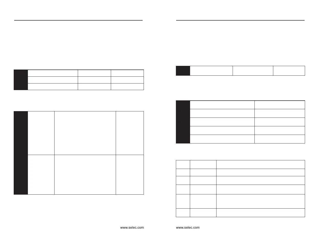
Input terminal X1 delay time
0.0s〜3600.0s
Default:0.0s
Input terminal X2 delay time
0.0s〜3600.0s
Default:0.0s
Input terminal X3 delay time
0.0s〜3600.0s
Default:0.0s
P4-35
P4-36
P4-37
Currently only X1, X2, and X3 have the function of setting the delay time.
It is used to set the delay time for the inverter to change the state of the
input terminal.
Input terminal
valid
mode
selection 1
Default:00000
Input terminal
valid mode
selection 2
Default:00000
Ones place: X1
Tens place: X2
Hundreds place: X3
Thousands place: X4
Ten thousand: X6
0: The X terminal is connected to
COM and the disconnection is
invalid.
1: X terminal and COM connection
are invalid, the disconnection
is valid.
P4-38
P4-39
Ones place:X5
Tens place:X7
Hundreds place:X8
Thousands place:X9
0: The X terminal is connected to
COM and the disconnection is
invalid.
1: X terminal and COM connection
are invalid, the disconnection
is valid.
1 : Inverse logic, the corresponding terminal is invalid when connected to
COM, and the disconnection is valid.
Used to set the active status mode of the digital input terminal.
0 : Positive logic, the corresponding terminal is valid when connected to
COM, and the disconnection is invalid.
P5: Output terminal
The inverter comes standard with one multi-function analog output
terminal, one multi-function digital output terminal, one multi-function relay
output terminal, and one FM terminal (optional as a high-speed pulse output
terminal, or as a collector open circuit) Switch output). If the above output
terminal does not meet the field application, you need to select the multi-
function input and output expansion card.
Y2 output mode selection
0: Pulse output
1: Switch output
Default:0
P5-00
The Y2 terminal is a programmable multiplexing terminal that can be used
as a high-speed pulse output terminal or as an open collector output terminal.
As a pulse output, the maximum frequency of the pulse is 100 kHz, see P5-
06.
Y2 switching output function selection
Default: 0 Has no function
Relay output function selection
Default: 2 Fault output (stop)
Relay 2 output selection (extended)
Default: 0 Has no function
Y1 output function selection
Default: 1 Inverter running
signal output
Y3 output selection (extended)
Default: 4 Frequency reached
P5-01
P5-02
P5-03
P5-04
P5-05
The above function code is used to select the function of 5 digital outputs.
The function of the multi-function output terminal is as follows:
Setting
value
Function Instruction
0
No function
Output terminal has no function
1
Inverter running
When the inverter is running (can be 0Hz),
it outputs ON signal.
2
Fault output
(stop)
When the inverter fails and the fault stops,
the ON signal is output.
3
Frequency-level
detection FDT1
output
Please refer to the description of function codes
P8-19 and P8-20.
4
Frequency
reached
Please refer to the description of function code P8-21.
Chapter 6 Chapter 6

 Loading...