User Manual
164
User Manual
165
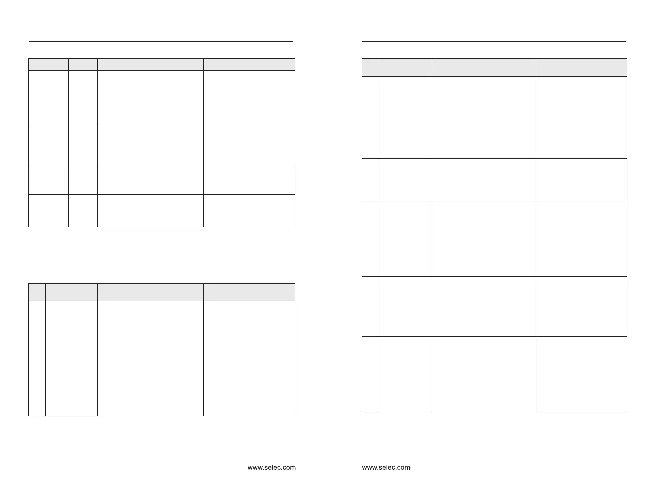
Motor
overheat
Err45
Initial
position
fault
Err51
The motor parameters are not
set based on the actual
situation.
Check that the motor
parameters are set
correctly and whether the
setting of rated current is
too small.
Braking
unit
overload
Err61
Resistance of braking resistor is
too small.
Replace a braking resistor
of larger resistance.
Short-
circuit
of braking
circuit
Err62
Braking IGBT is abnormal.
Contact the agent or
company to support.
1: The cabling of the
temperature sensor becomes
loose.
2: The motor temperature is too
high.
1: Check the temperature
sensor cabling & eliminate
the cabling fault.
2: Lower the carrier
frequency or adopt other
heat radiation measures.
Fault name
Display
Troubleshoot the cause
Solutions
7-2 Common faults and solution
Table 7-1 Common faults and solutions
The following fault conditions may be encountered during the use of the
inverter. Please refer to the following method for simple fault analysis.
No.
Solutions
Fault
phenomenon
Possible Causes
1
There is no
display at
power-on.
2
“FZKJ” is
displayed at
power-on.
3
“Err23” is
displayed at
power-on.
4
The inverter
display is
normal upon
power-on.
But “FZKJ” is
displayed
after running
and stops
immediately.
5
Err14 (IGBT
overheat)
fault is
reported
frequently.
6
The motor
does not
rotate after
the inverter
runs.
1: There is no power supply to
the inverter or the power input
to the inverter is too low.
2: The power supply of the
switch on the driver board of the
inverter is faulty.
3: The rectifier bridge is
damaged.
4: The control board or the
operating panel is faulty.
5: The cable connecting the
control board and the driver
board and the operating panel
breaks.
1: Check the power supply.
2: Check the bus voltage.
3: Re-connect the 8-core
and 34-core cables.
4: Contact the agent or
company to support.
No.
Solutions
Fault
phenomenon
Possible Causes
1: The cable between the driver
board and the control board is
in poor contact.
2: Related components on the
control board are damaged.
3: The motor or the motor cable
is short circuited to the ground.
4: The HALL device is faulty.
5: The power input to the
inverter is too low.
1: Re-connect the 8-core
and 34-core cables.
2: Contact the agent or
company to support.
1: The motor or the motor
output cable is short-circuited
to the ground.
2: The inverter is damaged.
1: The cooling fan is damaged
or locked-rotor occurs.
2: The external control terminal
cable is short circuited.
1: The setting of carrier
frequency is too high.
2: The cooling fan is damaged,
or the air filter is blocked.
3: Components inside the AC
drive are damaged (thermal
coupler or others).
1: Measure the insulation
of the motor and the output
cable with a megger.
2: Contact the agent or
company to support.
1: Replace the damaged
fan.
2: Eliminate external fault.
1: Reduce the carrier
frequency (P0-15).
2: Replace the fan and
clean the air filter.
3: Contact the agent or
company to support.
1: Check the motor and the
motor cables.
2: The AC drive parameters are
set improperly (motor
parameters).
3: The cable between the driver
board and the control board is
in poor contact.
4: The driver board is faulty.
1: Ensure the cable
between the inverter and
the motor is normal.
2: Replace the motor or
clear mechanical faults.
3: Check and re-set motor
parameters.
Chapter 7
Chapter 7

 Loading...