User Manual
180
User Manual
181
When the function code is set to time value, if the interval time between the
communication and the next communication is beyond the communication
timeout, the system will report communication failure error (Err16). At normal
circumstances, it will be set as invalid. If in the continuous communication
system, set this parameter, you can monitor the communication status.
Pd-05
30
Communication protocol
selection
Ones place:MODUBS
0: Non-standard Modbus protocol
1: standard Modbus protocol
Setting range
Default
Pd-05=30:When reading a command, the slave returns one byte more than
the standard Modbus protocol.
Pd-05=31:Choose the standard Modbus protocol.
Pd-06
9
Communication read
current resolution
0:0.01A
1:0.1A
Setting range
Default
The output unit used to determine the current value when the communication
reads the output current
Appendix B Brake resistor selection
The external braking resistor belongs to the energy-consuming braking
mode, and its energy will be completely dissipated in the power braking
resistor. Therefore, the power of the braking resistor and the choice of
resistance must be reasonable and effective. The following are the
recommended braking resistor power and resistance values for this drive.
According to the load, the user can change the value appropriately, but it
cannot be less than the minimum required by the inverter.
During the running process of the inverter, if the speed of the controlled
motor drops too fast, or the motor load shakes too fast, its electromotive force
will reverse the internal capacitance of the inverter through the inverter, so
that the voltage across the power module is pumped up, which is easy.
Damage to the inverter. The internal control of the inverter will suppress this
situation according to the load situation. When the braking performance does
not meet the customer's requirements, an external braking resistor is needed
to achieve timely release of energy.
Inverter power
Braking Unit
Recommended
resistance value
Minimum
resistance
Number
Built-in
(standard)
3.7KW-415V 400W
≥ 130Ω
1
5.5KW-415V 500W
≥ 90Ω
1
7.5KW-415V 800W
≥ 65Ω
1
11KW-415V
1KW
≥ 43Ω
1
15KW-415V 1.3KW
≥ 32Ω
1
18.5KW-415V 1.5KW
≥ 25Ω
1
22KW-415V 1.5KW
≥ 22Ω
1
30KW-415V 2.5KW
≥ 16Ω
1
37KW-415V 3.7kW
≥ 12.6Ω
1
45KW-415V
4.5kW
≥ 9.4Ω
1
55KW-415V
5.5kW
≥ 9.4Ω
1
Chapter 9
Chapter 9
Inverter power
Braking Unit
Recommended
resistance value
Minimum
resistance
Number
0.75KW-220V
Built-in
(standard)
80W
≥ 80Ω
1
1.5KW-220V 200W
≥ 55Ω
1
2.2KW-220V 200W
≥ 35Ω
1
3.7KW-220V 300W
≥ 25Ω
1
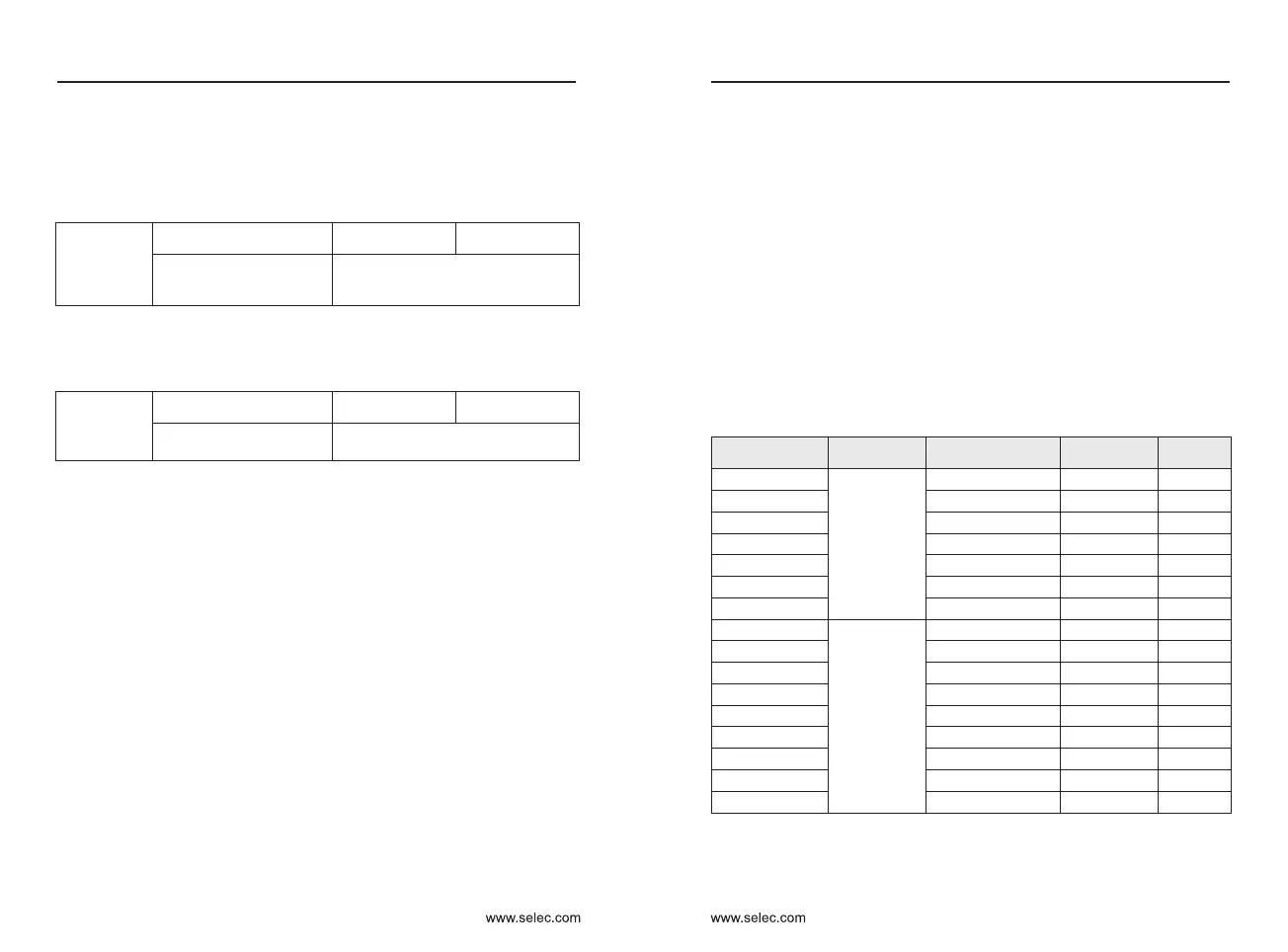
Inverter power
Braking Unit
Recommended
resistance value
Minimum
resistance
Number
0.75KW-380V
Built-in
(standard)
150W
≥ 300Ω
1
1.5KW-380V 150W
≥ 220Ω
1
2.2KW-380V 250W
≥ 200Ω
1
3.7KW-380V 400W
≥ 130Ω
1
5.5KW-380V 500W
≥ 90Ω
1
7.5KW-380V 800W
≥ 65Ω
1
11KW-380V
1KW
≥ 43Ω
1
15KW-380V 1.3KW
≥ 32Ω
1
18.5KW-380V 1.5KW
≥ 25Ω
1
22KW-380V 1.5KW
≥ 22Ω
1
30KW-380V
External
2.5KW
≥ 16Ω
1
37KW-380V 3.7kW
≥ 12.6Ω
1
45KW-380V
4.5kW
≥ 9.4Ω
1
55KW-380V
5.5kW
≥ 9.4Ω
1
75KW-415V
7.5kW
≥ 6.3Ω
1
90KW-415V
4.5kW
≥ 9.4Ω
2
110KW-415V
5.5kW
≥ 9.4Ω
2
132KW-415V 6.5kW
≥ 6.3Ω
2
147KW-415V 16kW
≥ 6.3Ω
2
External
Note:When the braking resistor is working, the surface has high voltage and
high temperature. Please consider the safety and flammability of the
surrounding environment when installing.

 Loading...