User Manual
124
User Manual
125
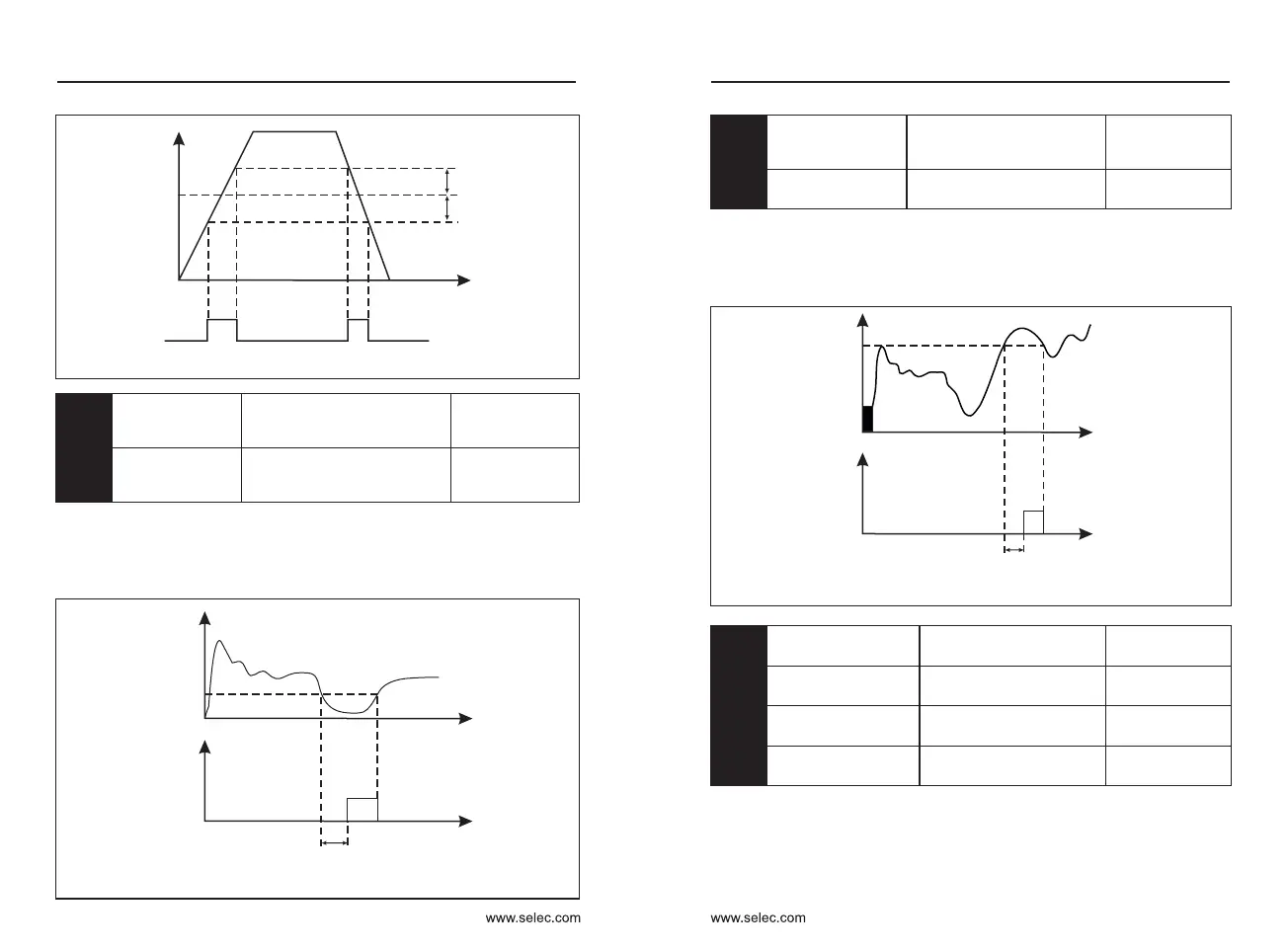
Figure 6-22 Schematic diagram of arbitrary arrival frequency detection
Running frequency
Arbitrary arrival
frequency
Frequeny
detection width
Time
OFF OFF OFF
ON ON
P8-34
Zero current
detection level
0.0%~300.0%
100.0% corresponds to
the rated current of the motor
Default:5.0%
P8-35
Zero current
detection delay
time
0.01s〜600.00s
Default:0.10s
When the output current of the inverter is less than or equal to the zero
current detection level and the duration exceeds the zero current detection
delay time, the inverter outputs ON signal. Figure 6-23 Schematic diagram of
zero current detection.
Figure 6-23 Schematic diagram of zero current detection
Output current
Zero current detection
level IP8-34
Zero current detection
signal
Time
Time
ON
OFF
Zero current detection delay time P8-35
P8-36
Output
overcurrent
threshold
0.0% (not detected)
0.1%~300.0%
motor rated current
Default:200.0%
P8-37
Output overcurrent
detection delay time
0.00s〜600.00s
Default:0.00
When the output current of the inverter is greater than or exceeds the
detection point and the duration exceeds the software over-current detection
delay time, the inverter outputs an ON signal. Figure 6-24 shows the output
current over-limit function.
Figure 6-24 Schematic diagram of output current overrun detection
Output current
Output current limit
P8-36
Output current overrun
detection signal
Time
Time
ON
Output current overrun
detection delay time P8-37
Arbitrary arrival
current 1
0.0% to 300.0%
(rated motor current)
Default:100.0%
Arbitrary current 1
width
0.0% to 300.0%
(rated motor current)
Default:0.0%
Arbitrary arrival
current 2
0.0% to 300.0%
(rated motor current)
Default:100.0%
Arbitrary current 2
width
0.0% to 300.0%
(rated motor current)
Default:0.0%
When the output current of the inverter is within the positive and negative
detection width of any set current, the inverter outputs an ON signal.
P8-38
P8-39
P8-40
P8-41
Chapter 6 Chapter 6

 Loading...