User Manual
Chapter 3
MC
R/L1
S/L2
T/L3
R
S
T
X1
X2
X3
X4
X5
X6
COM
Input terminal 1
+10V
AI1
AI2
GND
PE
Frequency given
0-10V
0-20mA Input
0-10V Input
J4 jumper
Frequency setting
power supply
Multi-function
analog inout
W
V
U
PE
QF
(+)/B1
B2
(-)
Braking unit
BR
Analog output
0-10V/0-20mA
RY1
ROA
ROB
ROC
Relay output
RY2
M
Breaker pull-in,
current less than 30A
0-10V
AI2
0-20mA
J5 jumper
0-10V
AO
0-20mA
+24V
Y1
Y2
BR
External keyboard port
J13
FWD
REV
External fault
Multi-pase reference
velocity 1
Default:Running
frequency
Default:
running
indication
Default:
Direction
indication
(Default: Fault output)
Potentio-
meter
3-5K
Common terminal
AO
GND
485+
485-
GND
RS485
communication
Braking resistor
Input terminal 2
Input terminal 3
Input terminal 4
Input terminal 5
Input terminal 6
Multi-pase reference
velocity 2
Multi-pase reference
velocity 3
Default
settings
3 phase power supply
Single phase 220V inverter
input connect with L N
415V±15%, 50/60Hz
PE
User Manual
Chapter 3
11
10
3-3-2 Connection of inverter output terminals U, V, W
Ÿ The inverter output terminals are connected to the 3-phase motor in the
correct phase sequence. If the motor rotates in the wrong direction, the
wiring of any two phases of U, V, and W can be exchanged.
Ÿ The output side of the inverter cannot be connected to the capacitor and
the surge absorber.
Ÿ When the wiring between the inverter and the motor exceeds 50 meters,
the distributed capacitance between the lines will generate a large
leakage current, which may cause the inverter to over-current trip. At the
same time, in order to avoid damage to the motor insulation, the output
reactor must be compensated. .
Ÿ If the installation location of the inverter is quite sensitive to interference,
please install an output noise filter to reduce the carrier frequency of the
inverter and reduce interference.
3-3-3 Braking resistor and brake unit connection
Ÿ When the load inertia is large and it is necessary to stop frequently or stop
for a short time, when the braking capacity of the inverter is insufficient or
to increase the braking torque, etc., the braking resistor or the braking
unit may be selected as needed.
Ÿ When the inverter has no built-in braking unit, the main circuit (+) and (-)
terminals are connected to the external braking unit.
Ÿ Do not connect the main circuit (+) and (-) terminals to the braking
resistor.
Ÿ The main circuit B1, B2 terminal is connected to the braking resistor
(there is B1, B2 terminal indicates that the inverter has built-in braking
unit).
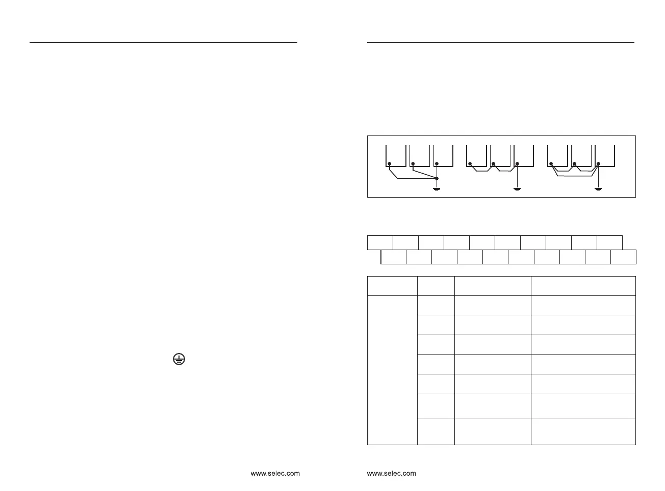
3-3-4 Inverter Grounding Terminal PE
Ÿ For safety and noise reduction, the ground terminal PE of the inverter
must be well grounded.
Ÿ Use the specified standard grounding wire and be as short and thick as
possible (grounding impedance 10Ω or less).
Ÿ The grounding wire of the inverter must not be grounded together with
large current loads such as electric welders and high-power motors, but
must be grounded separately.
Ÿ The power supply line generally adopts 5 core wires, of which 3 are fire
wires, 1 neutral wire, and 1 ground wire. It is strictly forbidden to use the
neutral wire as ground wire.
Ÿ When multiple inverters are installed together, all inverters must be
directly connected to the common ground.
(a) correct (b) not recommend (c) error
3-4 Control circuit terminal description
Terminal description &
default setting
Classification
Mark
Terminal name
Multi-functional
input
X1
X2
X3
X4
X6
COM
Multi-functional input
terminal 1
Default setting : Forward
Multi-functional input
terminal 2
Default setting : Reverse
Multi-functional input
terminal 3
Default setting : No function
Multi-functional input
terminal 4
Default setting : No function
Multi-functional input
terminal 6
Default setting : No function
can be used as a high
speed pulse input
Public terminal
Multi-functional input common
+24V power supply
reference groung
CN1
Needle base
COM
X5
RS485
485- 485+
8 7 6 543 2 1
6 543
Please refer to the following illustration:
+24V
Y1 Y2
X1 X2
X3
X4 AO
485- 485+
ROA ROB ROC COM
X5
X6
GND
AI1 AI2
+10V
X5
Multi-functional input
terminal 5
Default setting : No function
 Loading...
