User Manual
174
User Manual
175
Number of function code(H)
It is the number of function codes read by this frame.
If it is 1, it indicates that one function code is read.
During transmission, low bytes follow high bytes.
In the present protocol, only one function code is read
once, and this field is unavailable.
Number of function code(L)
Data(H)
It is the response data or data to be written. During
transmission, low-order bytes follow the high-order
bytes.
Data(L)
END
It is 3.5-byte transmission time.
CRC Checking
In RTU mode, messages include an error-checking field that is based on a
CRC method. The CRC field checks the contents of the entire message. The
CRC field is two bytes, containing a16-bit binary value. The CRC value is
calculated by the transmitting device, which appends the CRC to the
message. The receiving device recalculates a CRC during receipt of the
message, and compares the calculated value to the actual value it received in
the CRC field.
If the two values are not equal, that means transmission is error
The CRC is started by 0xFFFF.Then a process begins of applying
successive eight-bit bytes of the message to the current contents of the
register. Only the eight bits of data in each character are used for generating
the CRC. Start and stop bits, and the parity bit, do not apply to the CRC.
During generation of the CRC, each eight-bit character is exclusive Oared
with the register contents. Then the result is shifted in the direction of the least
significant bit (LSB), with a zero filled into the most significant bit (MSB)
position. The LSB is extracted and examined. If the LSB was a 1, the register
is then exclusive Oared with a preset, fixed value. If the LSB was a 0, no
exclusive OR takes place. This process is repeated until eight shifts have
been performed. After the last (eighth) shift, the next eight-bit byte is exclusive
Oared with the register's current value, and the process repeats for eight
more shifts as described above. The final contents of the register, after all the
bytes of the message have been applied, is the CRC value.
When the CRC is appended to the message, the low-order byte is
appended first, followed by the high-order byte. Unsigned int crc_chk_value
(unsigned char *data_value, unsigned char length
}
int I;
for(i=0;i<8;i++)
{
{
unsigned int crc_value=0xFFFF;
else
{
{
{
}
}
while(length--)
crc_value^=*data_value++;
if (crc_value&0x0001)
crc_value=(crc_value>>1)^0xa001;
crc_value=crc_value>>1;
}
}
return (crc_value);
Definition of communication parameter address
Read and write function-code parameters (Some functional code is not
changed, only for the manufacturer use.)
The group number and mark of function code is the parameter address
for indicating the rules.
High level bytes: P0~PP (Group P), A0-AF (Group A), 70-7F (Group U)
Low level bytes: 00 to FF
For example, to read parameter P3-12, communication address of P3-12 is
expressed as 0xF30C.
Note:
Some parameters cannot be changed during operation, some
parameters regardless of what kind of state the inverter in, the parameters
cannot be changed. Change the function code parameters, pay attention to
the scope of the parameters, units, and relative instructions.
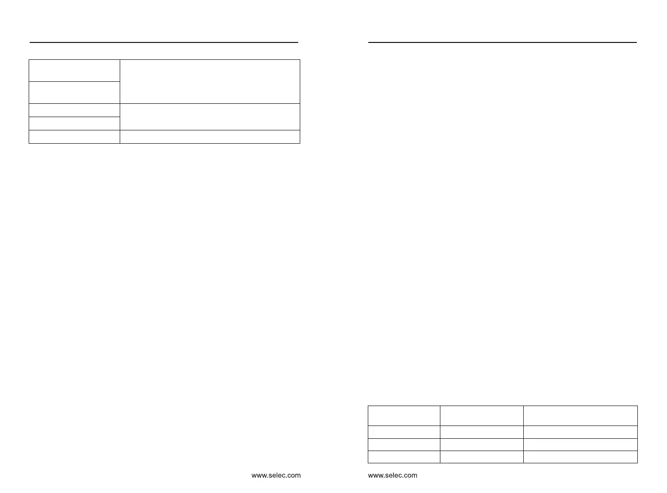
Function code group
Communication
inquiry address
Inquiry address When
Communication modifies RAM
P0〜PP 0xF000〜0xFFFF 0x0000〜0x0FFF
A0〜AF 0xA000〜0xAFFF
0x4000〜0x4CFF
U0 Group
0x 7000〜0x 70FF
Chapter 9
Chapter 9

 Loading...