EasyManuals Logo

SELFSAT SNIPE 3 User Manual

SELFSAT SNIPE 3
61 pages
To Next Page IconTo Next Page
To Previous Page IconTo Previous Page
Page #26 background imageLoading...
Page #26 background image
GERMAN - 5
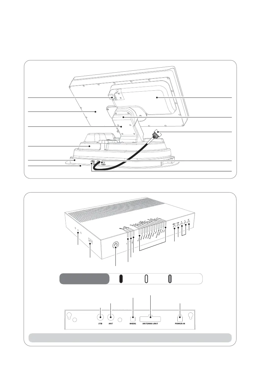
2-2. Teilebezeichnung
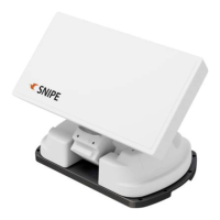
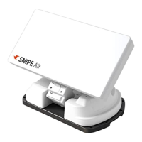
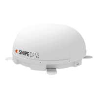
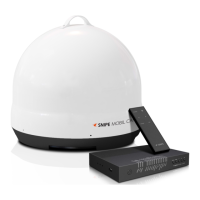
Haupteinheit
Verriegelung
Antenne
Erhebung
Hauptkörper
Sockel
Montageplatte
LNB
Neigunng/Drehung
zum Controller-Kabelanschluss
(vorgeschaltet)
zu STB (optional)
zu Controller ("ANT" Port)
Controller
• Vorderseite
• Rückseite
EinLED-Anzeie
Netzschalter
USB-Anschluß
Reglerhalterung Loch
HOME-LED
Lock-LED
DiSEqC-LED
Satelliten-LEDs
DiSEqC-Taste
HOME-Taste
Pfeiltasten
SET -Taste
FlimmerAus
STB-Kabel zum STB
Signalkabel zur Haupteinheit
DIP-Schalter (Betriebsartenschalter)
Controllerkabel vor Haupteinheit
Stromversorgung
Hinweis: Für den Normalbetrieb sollen DIP-Schalter in der MODE in der oberen Position sein.

Questions and Answers:

Question and Answer IconNeed help?

Do you have a question about the SELFSAT SNIPE 3 and is the answer not in the manual?

SELFSAT SNIPE 3 Specifications

General IconGeneral
Frequency Range10.7 - 12.75 GHz
PolarizationLinear (Horizontal/Vertical)
Azimuth Range360°
Satellite SystemsDVB-S2, DVB-S
Gain33.7 dBi @ 12.7 GHz
Power Supply12 - 24 V DC
LNB Output1
Temperature Range-20°C to 60°C
Antenna TypeFlat Panel Antenna

Related product manuals