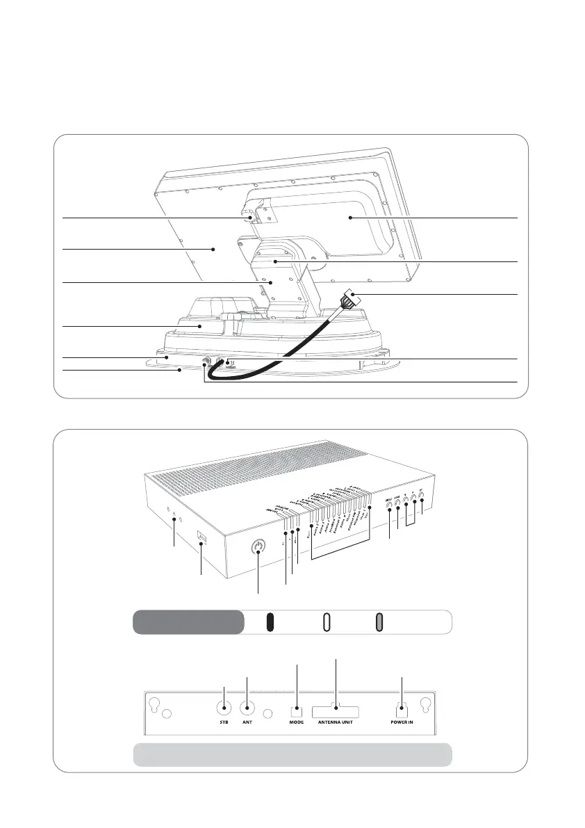
EasyManuals Logo

SELFSAT SNIPE 3 User Manual

SELFSAT SNIPE 3
61 pages
To Next Page IconTo Next Page
To Previous Page IconTo Previous Page
Page #6 background imageLoading...
Page #6 background image
ENGLISH - 5
2-2. Name of parts
Main unit
Latch
Antenna
Elevation
Main body
Base
Mounting plate
LNB
Skew pivot
to Controller cable connection
(pre-connected)
to STB (optional)
to Controller ("ANT" port)
Controller
• Front
• Back
OnLED Indicator
Power S/W
USB port
Controller bracket hole
HOME LED
Lock LED
DiSEqC LED
Satellite LEDs
DiSEqC button
HOME button
Arrow buttons
SET button
BlinkingO
STB cable to STB
Signal cable from Main unit
Dip switch (Mode selector)
Controller cable from Main unit
Power port
Note : For normal operation, Dip switches in MODE should be up

Questions and Answers:

Question and Answer IconNeed help?

Do you have a question about the SELFSAT SNIPE 3 and is the answer not in the manual?

SELFSAT SNIPE 3 Specifications

General IconGeneral
Frequency Range10.7 - 12.75 GHz
PolarizationLinear (Horizontal/Vertical)
Azimuth Range360°
Satellite SystemsDVB-S2, DVB-S
Gain33.7 dBi @ 12.7 GHz
Power Supply12 - 24 V DC
LNB Output1
Temperature Range-20°C to 60°C
Antenna TypeFlat Panel Antenna

Related product manuals