EN
23
Installation and electrical connection
3. Installation and electrical connection
Warning!
Caution! Risk of injury through an electric shock!
Connection only when de-energised!
Run the motor only after installation
3.1. Installation of the motor into a shaft
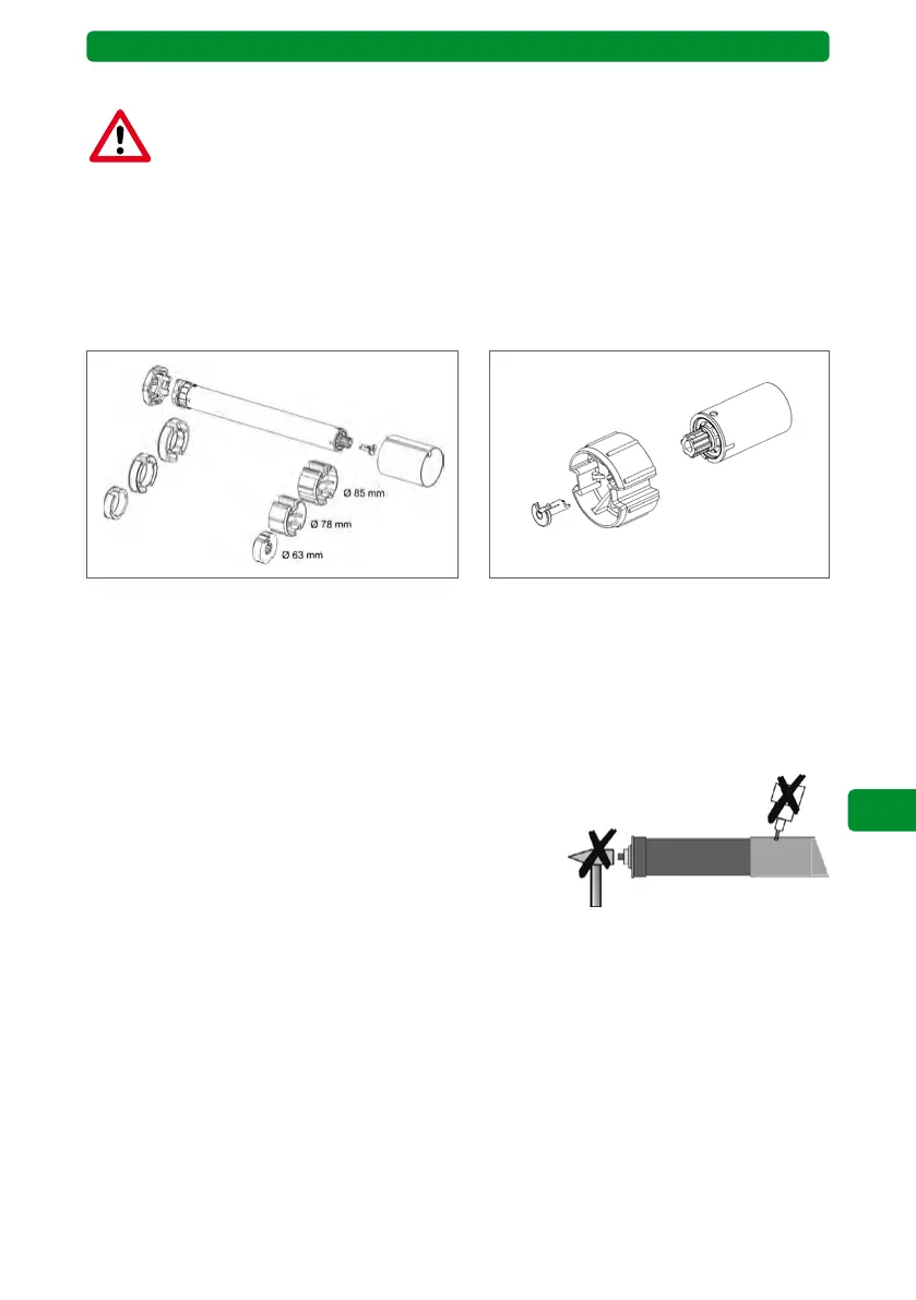
1. Crown and coupling adapter need to be determined according to the size of the shaft
(picture 1).
2. Push the crown adapter over the shaft and position it precisely on the motor head.
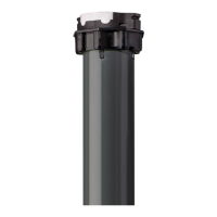
3. Slide the coupling and plug-in the coupling locking device (picture 2).
Picture 1: Examples for different shaft sizes Picture 2: Coupling locking device*
* For drives of series 2 with 40/50 Nm and series 3 the coupling will be secured with a ring
(security ring according to DIN 471-20x1,20 FST, article number 940516). To fix the security
ring a special security ring pliers for shafts with eyelet size < 2 mm is necessary!
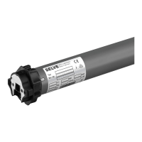
4. Push the motor into the shaft in a positive-locking way. The motor must not be subject to
any impacts. Crown and coupling adapters must not have any play inside the shaft.
5. Where required, secure the motor axially, e.g. by screwing the shaft to the coupling adapt-
er. Do not drill holes into the motor area!
6. Attach the shaft with the motor and the shaft cap in the bearings. Do not bend the motor
cable and place it so that it cannot be damaged. To keep water from getting into the motor,
place the motor line in a bend direction downwards, so that any water can drip off.
7. Attach the curtain to the shaft.