ENGLISH
Pag. 27
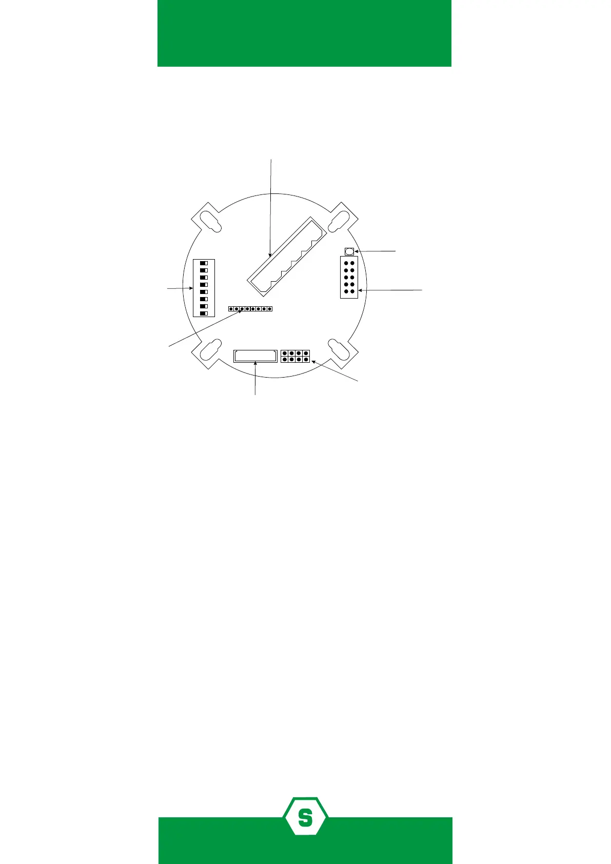
5.4 Main board layout
ON
Terminal for connections
1 2 3 4 5 6
1 3 5 7
2 4 6 8
JP4: Connector
Rs485 board or 1 relay board
Dip-switch to set
thresholds’ alarm and detector adress
JP5: Connector sensing element
2 RS485 A
3 RS485 B
4 Gnd
5 +Vcc 12-24V
6 +/- 4-20 mA OUT
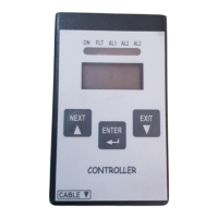
JP7 Connector
calibration keypad or display or 3 relay board
status LED
JP9:
Pin 1-2 Not to be used
Pin 3-4 Open: Modbus Standard communication protocol
Pin 3-4 Closed: Proprietary protocol tipically used by Multiscan IDI
version 3.00 or before
Pin 5-6 Open: Enables auxiliary boards and display LEDs
Pin 5-6 Closed: Disables auxiliary boards and display LEDs
Pin 7-8 Open: New SMART 3G functionalities
Pin 7-8 Closed: Old SMART 3G functionalities
1 2 3 4 5 6 7 8
*
* Pin 7-8 are only available on the red version PCB
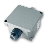
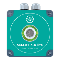
5.5 Detector conguration
The detector provides a 4-20 mA proportional output. It is also possible to have detectors
daisy chained on RS485 bus lines. In that case, it is necessary to have the optional RS485
interface model STS/IDI mounted in the detector.
It is possible to provide the detector with optional outputs by inserting the following optio-
nal cards:
³ STS1REL 1 relay board (non-latching relay)
³ STS3REL 3-relay board (non-latching relay)
To activate the outputs provided by the above boards, it is necessary to open the jumper JP9
on pin 5-6 on the main PCB. If the jumper JP9 is not opened on pin 5-6, it won’t be possible
to connect the above optional output boards.
Figure 1) Main board layout