ENGLISH
Pag. 28
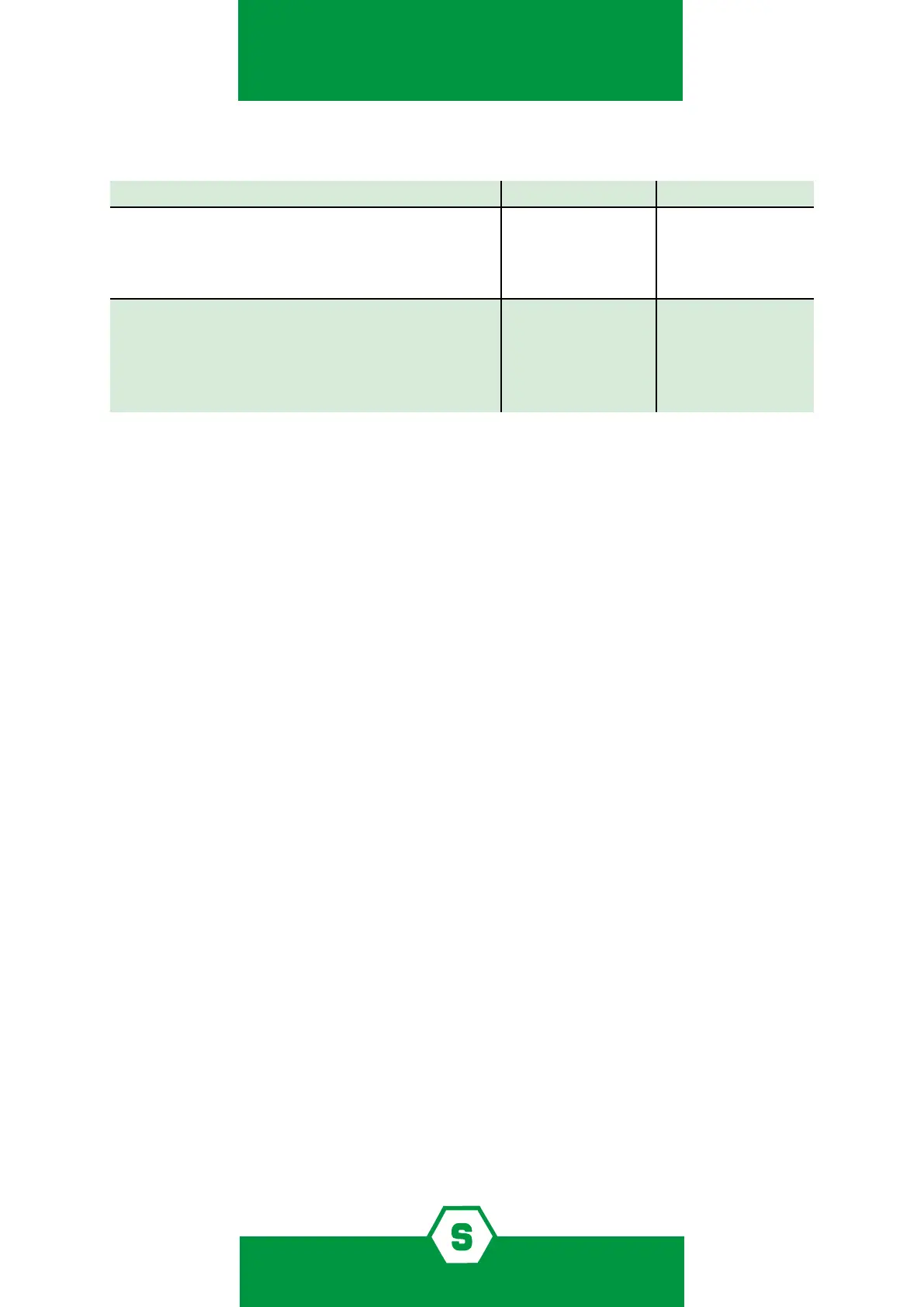
Table 4) Functional properties when the pin 5-6 of JP9 jumper is in open or closed position
Properties Pin 5-6 open Pin 5-6 closed
4-20 mA output as per default conguration
Fault 2 mA
Underscale 3 mA (required for the connection of
gas detectors to MULTISCAN++ control panels)
- - YES
Analog 4-20 mA
Fault 2 mA
Overrange 21 mA
Connection to optional boards
LED visualization on display board
YES - -
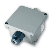
5.6 4-20 mA output connection
³ Use shielded cables.
³ Wires’ cross section depends on the distance between the control panel and the detec-
tor: for a distance up to m 100 we advise a 3-core wire with cross section area of 0.75
mm2; for a distance between m 100 and 200 we recommend a 3-core wire with cross
section of 1.0 mm2; for a distance between m 200 and 300 we recommend a 3-core
wire with cross section 1.5 mm2.
³ Should any junctions be necessary on wires, please make sure there is no interruption
on the shield.
³ Please remember that the shield is to be grounded from the control panel side only.
Also remember never to connect the shield to the detectors.
³ Ensure the wire connections, either clutching or crimping type, are properly carried
out with terminals that do not oxidise or loosen. We recommend having them solde-
red.
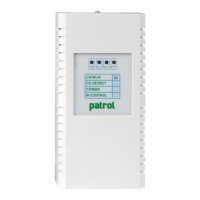
³ The SMART3G gas detectors can be connected to control panels available on the mar-
ket having 4-20mA input signals.
³ Please make sure the panels are certied according to the standards EN60079-29-
1:2016.
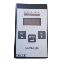
Figure 2 shows the connection of a SMART3G detector to a control panel. Control panels
accepting 4-20 mA input signals allow the connection of only one detector per input.