ENGLISH
Pag. 32
Testing / initial checking and calibration should be carried out by using a gas mixture in the
appropriate range, along with our calibration kit.
In order to execute this operation, the user has to ask for the proper test gas bottle and
connect to this the valve with owmeter. Connect a pipe with adequate diameter, which
connects to the calibration adapter for the gas detector. The calibration of the detector is
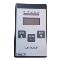
made by handheld calibration keypad or detector display. See paragraph 10 for more details
about the accessories for calibration.
Please consult the specic instruction manuals (display, keypad and eld calibration kit) for
further information on use.
6.3 Use
The detector works autonomously and automatically. Once adequately connected, no fur-
ther operations are required.
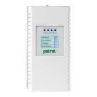
The ashing red LED on the motherboard indicates the detector’s working condition as de-
tailed in the following table.
Table 5) Flash rate in seconds with pin 5-6 of jumper JP9 open (default conguration)
Flash rate [s] Meaning
1 ON – 0,1 OFF Warm-up time
1 ON - 1 OFF Normal mode
ON Fault - W.D.
With pin 5-6 of jumper JP9 closed, should the measured gas concentration exceed 100% LFL,
the red LED on the PCB lights up, as to signal the FAULT status, while on the display all of the
LEDs light-up; output current will be forced to 21 mA.
To reset the detector to normal working conditions it will be necessary to turn the power of
the unit o and on.
Table 6) Flash rate in seconds with pin 5-6 of jumper JP9 closed
Flash rate [s] Meaning
1 ON – 0,1 OFF Warm-up time
1 ON - 1 OFF Normal mode
0,1 ON – 1 OFF Alarm 1
2 x 0,1 ON – 1 OFF Alarm 2
3 x 0,1 ON – 1 OFF Alarm 3
ON Over Range
ON Fault - W.D.
Note: The user cannot manually silence the alarm. However, it will be automatically silenced
when its cause won’t be present anymore.