ENGLISH
Pag. 29
ON
1 2 3 4 5 6
1 3 5 7
2 4 6 8
1 2 3 4 5 6 7 8
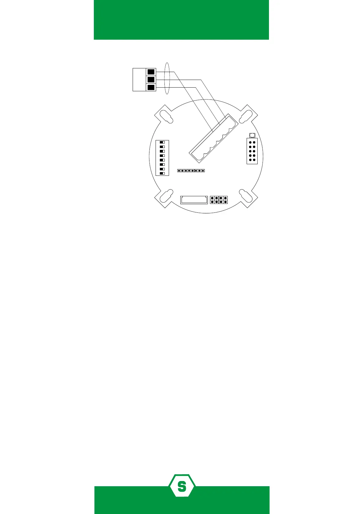
SHIELDED CABLE 3x0.75
CONTROL
UNIT TERMINAL BOARD
S
S
-
-
+
+
5.7 RS485 serial output connection (optional)
To connect SMART3G gas detectors to RS485 bus lines, it is necessary to have the RS485 in-
terface model STS/IDI plugged in the detectors. The connection of SMART3G to RS485 bus
lines should be performed by using a 4-wire cable, 1 pair for the RS485 bus and 1 for the
power supply. It is also necessary that:
³ Wiring between the detectors and the control panel should be made by using con-
nection cable EIA RS485: 2 core wires with section 0.22 / 0.35 mm2 and shield (twisted
pair). Nominal capacity between the wires <50pF/m, nominal impedance 120 . These
features can be found in BELDEN cable 9842 or similar (data transmission cable in EIA
RS485).
³ Using this wiring, the total length of the line should not exceed 1000 m.
³ Detectors and output modules are to be wired in daisy chain mode. We recommend
avoiding star or tree mode connection as interference immunity would be reduced.
³ Make sure that each multi-polar wire includes just one RS485.
³ Make sure that a 120 end line resistor is placed at the beginning and at the end (on
the last detector or output module) of the bus line.
³ For the detectors’ power supply connection, we recommend using a 2-wire cable with
suitable section according to the distance and number of detectors.
³ Once the installation has been completed, verify that each detector reaches at least
12 Vdc.
When the STS/IDI board is plugged in, the dip-switches on SMART3G motherboard are em-
ployed to set the detector address. To set the detectors’ address, please refer to the technical
Figure 2) Connection scheme for the 4-20 mA output