ENGLISH
Pag. 30
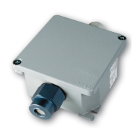
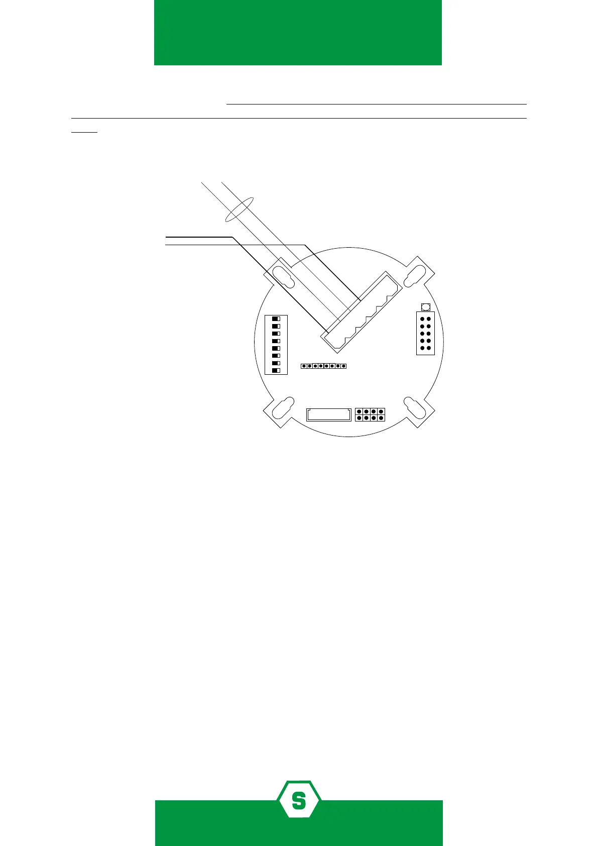
5.8 Connection to optional boards
By opening the 5-6 pin of JP9 jumper on the main PCB, it is possible to activate optional
outputs available when using the following cards:
³ ST.S3REL, three-relay card with tension free changeover contacts. One relay is associa-
ted to Fault and Watch-dog. The remaining two are to be associated to two outputs of
the three preset alarm thresholds.
³ ST.S1REL, one-relay card to oer one tension free changeover contact, to be either
associated to Fault or to Alarm status.
By modifying the dipswitch conguration on the motherboard, dierent alarm thresholds
might be obtained.
It is also possible to modify the relay intervention when using the 3-relay card, as per the
following gure. Relays are not-memorised and they are not time-limited. The user cannot
silence the alarm manually, it will silence automatically when the its cause won’t be present
anymore.
handbook of STS.IDI interface. With the calibration keypad is possible to set the detector’s
address, to memorise it the dip-switch must be in 0 position (all keys positioned in the ON
side).
Alarm thresholds will automatically set on the default conguration. When detectors are
RS485 connected, the proportional 4-20mA output remains active.
ON
1 2 3 4 5 6
1 3 5 7
2 4 6 8
1 2 3 4 5 6 7 8
-
+
+
-
A
B
B
A
Figure 3) Detector connection to RS485 bus lines