22 Chapter 3: Electrical Connections
WQG-10004-01 accuMAG Meter Quick Guide Software v4.1.2
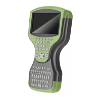
Figure 3-3:Cable connection at sensor side, standard cable
1. 1 Connect drain wires under screw.
2. 2 Connect shielding under clamp.
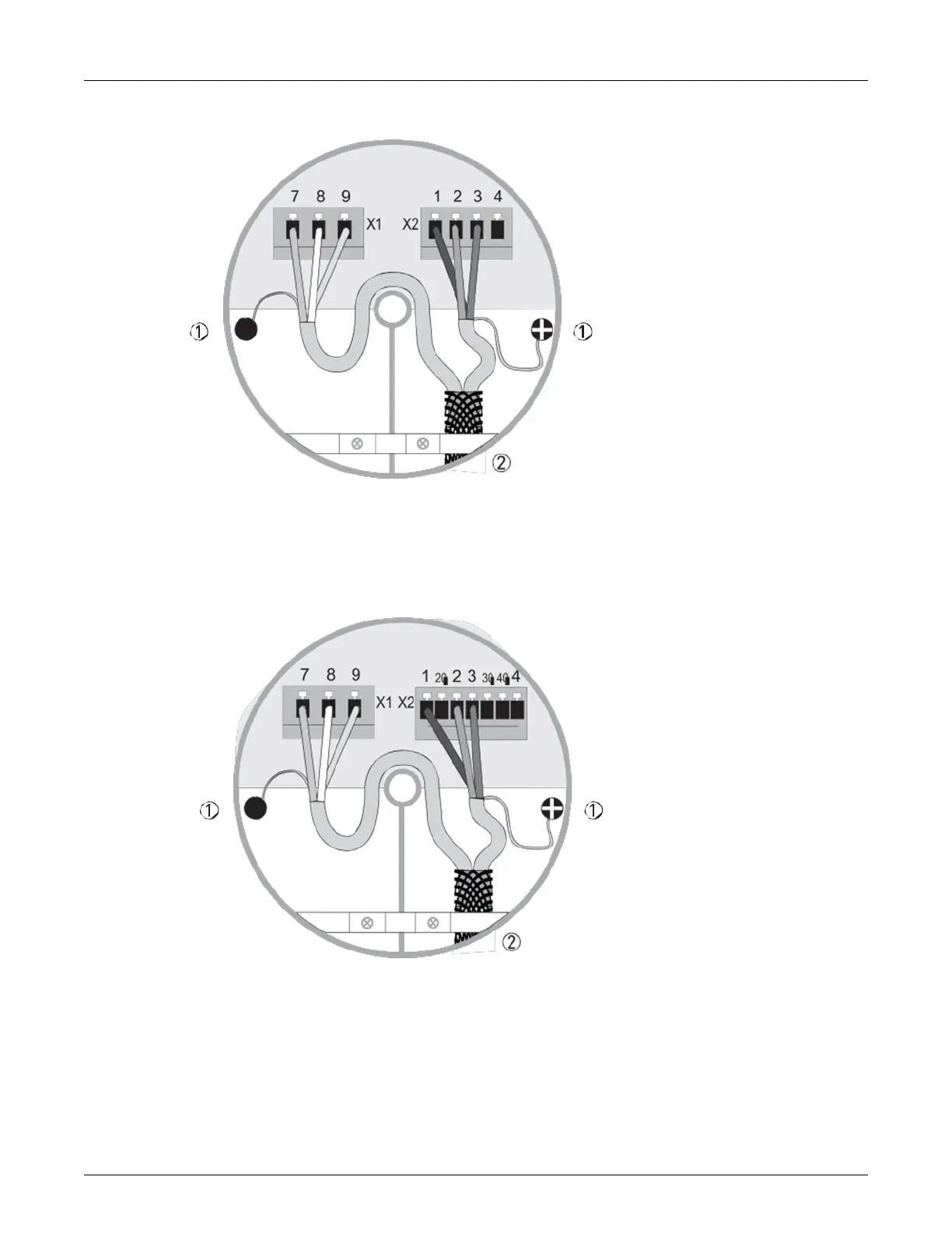
Figure 3-4: Cable connection at converter side, standard cable
1. Connect drain wires under screw.
2. Connect shielding under clamp.
a. Prepare appropriate cable lengths as shown.
b. Connect the wires as shown in the following table.
| sales@mvandc.com | Phone: 877.566.3837 | Fax: 925.407.2903
 Loading...