Operation Section 3
3-4
Part Number 020003996 4/12
Operation
Carbon Dioxide (CO
2
) leaves the storage tank and
arrives at the carbonator tank through the gas inlet.
Water supply enters the carbonator pump inlet at regular
street water line pressure (minimum 20 PSI, maximum
80 PSI, dynamic or flowing pressure). The water pump
increases the pressure of the water, which allows the
water to flow into the carbonator tank. The CO
2
and the
water mix together in the carbonator to produce the
carbonated water that is then sent to the soda dispenser.
The agitation of the water and CO
2
together in the tank
under high pressure creates the soda water. The quality
of carbonation (percent of CO
2
mixed in the water)
increases as the water temperature decreases and
exposure time increases.
The water level in the carbonator tank is controlled by a
water level control in the tank. This control turns the
pump motor off and on to maintain a preset level of liquid
in the tank. The water level control may be electronic
probes or a mechanical float.
SYRUP DELIVERY SYSTEM
Your syrup location can vary depending on the volume of
beverages served and ease of accessibility. Your
beverage system may set in a back storage room or
under the counter of the dispenser. Configurations are
almost limitless. Check the temperatures expected for
the storage location. Adverse temperatures can affect
the storage and quality of beverage products. It is
recommended the temperature of storage location must
not fall below 40°F (4°C) or rise above 90°F (32°C).
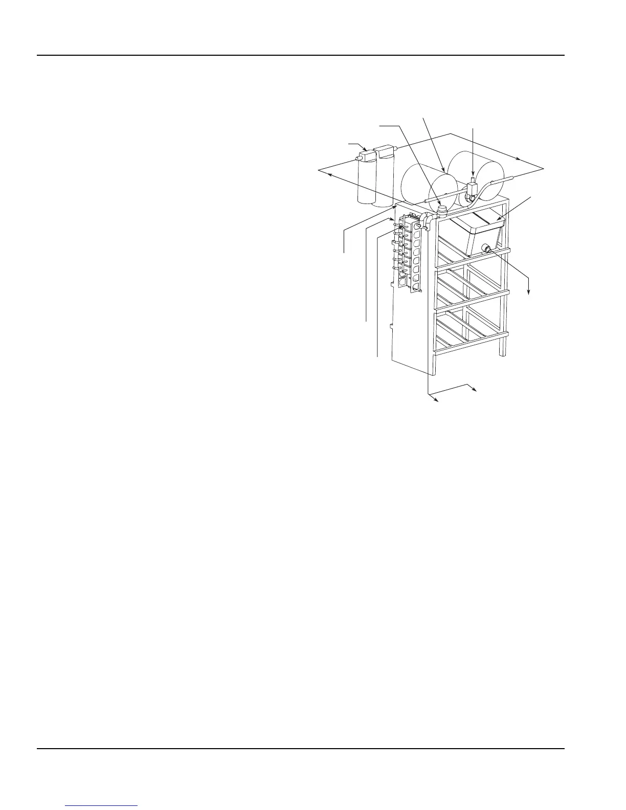
BACK ROOM PACKAGE
1. Incoming tap water – must be at a minimum
dynamic pressure of 40 psi and maximum static
pressure of 55 psi.
2. Carbonator Water pump motor – Powers the
water pump. The water pump motor is part of the
carbonator pump deck.
3. Carbonator Water pump – Pumps tap water into
the carbonator tank. The water pump is part of the
carbonator. The incoming water for the carbonator
must be first run through the pump before
connecting to the proper cold plate inlet.
4. Internal/External Carbonator tank – Combines
CO
2
gas and tap water to form carbonated water.
The “carbonator” is the carbonator tank, water pump
and water pump motor.
5. CO
2
cylinder – Holds highly pressurized carbon
dioxide (CO
2
). The CO
2
cylinder is a steel or
aluminum cylinder tank. CO
2
gas flows through the
primary pressure regulator.
6. BIB pressure gauge – Set for a minimum of 60 psi.
Indicates CO
2
pressure going to B-I-B pumps.
From Water Supply
To Noncarbonated
Water Inlet Barb
Water to
Carbonator
Pump
Filter
Water Regulator
40–55 PSI
Booster System
(If Required)
To CO
2
Manifold (BIB
Pumps) from
CO
2
Supply
60 PSI
To Syrup Inlet
Barbs on Unit
To BIB Pumps
from BIB
To BIB
Pump
BIB