Analyzer Start-Up Procedure DF-150E 13
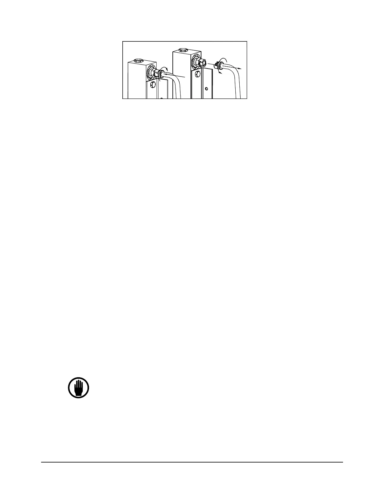
PUSH
ROTATE
PULL
ROTATE
Figure 3: Quick Disconnect
5.1.2 Add Electrolyte
1. Un-screw the lid from the sensor.
2. Add the entire contents of one bottle of Hummingbird Brand E-Lectrolyte
Blue to the sensor.
3. Replace the lid securely.
5.1.3 Re-install the Sensor
1. Attach the quick disconnect at the top of the flowmeter. (Skip this step if
the analyzer is equipped with the stainless steel outlet tubing option.)
2. Carefully slide the sensor into the analyzer.
3. Tighten the thumbscrews.
4. Re-connect the electrical cable to the sensor.
5. Replace the bulkhead nut on the inlet gas connection on the rear of the
analyzer. NOTE: After seating the nut finger tight, use a wrench to turn it
only an additional 10 degrees. Do not over tighten the bulkhead nut.
6. If the analyzer is equipped with the stainless steel outlet tubing option,
replace the nut on the outlet bulkhead fitting.
7. Allow the sensor to sit for 60 minutes before starting gas flow.
5.2 Making Sample Gas Connections
NOTE
For gas pressures between 1.0 and 5.0 psig use a high quality flow
control valve between the gas source and the analyzer to set the
flow rate.
You may have an optional Flow Control Valve mounted on the
sensor bracket and accessible behind the door (see “Flow Control
Valve” on page 24).
For gas pressures above 5 psig use a high quality pressure