42 DF-150E Outputs and Remote Connections
9.1 The I/O Connector
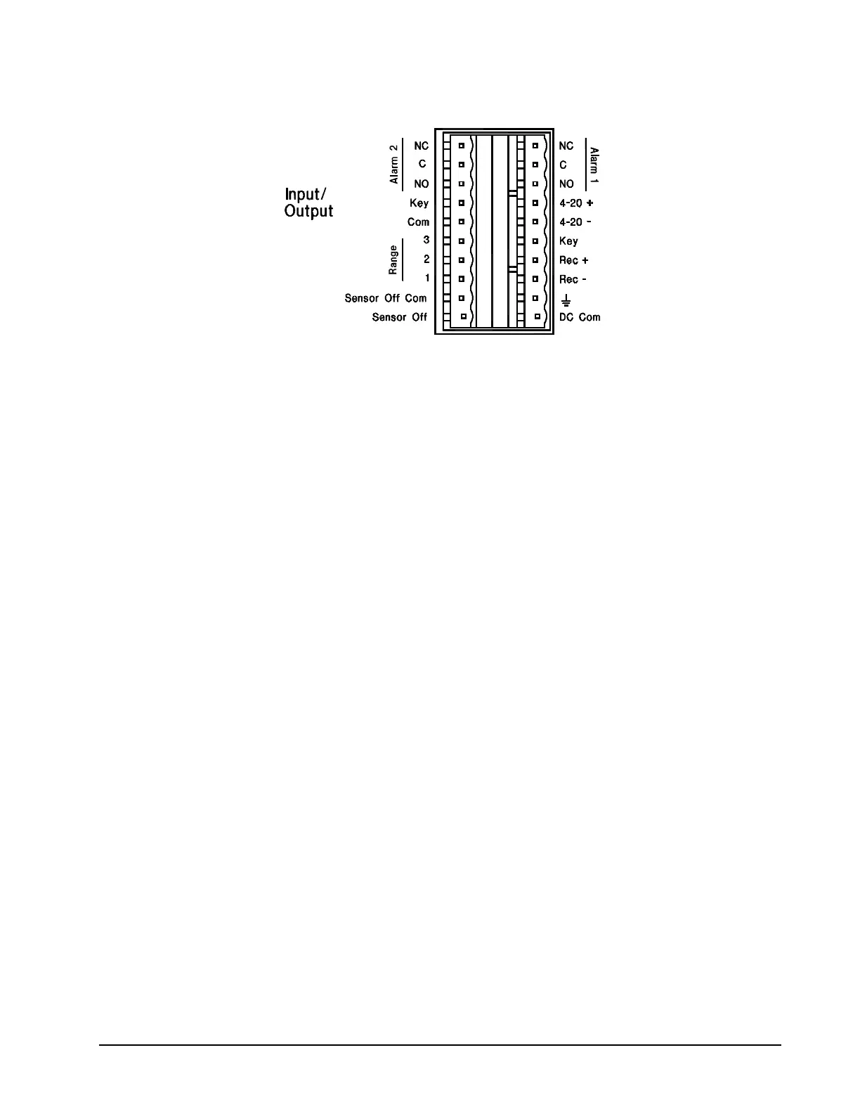
Figure 25: I/O Connector Pin-out
9.1.1 Alarm 1 and 2 (NC-C-NO)
Alarms are optional. Two alarms are available on the DF-150. Only “Alarm 1”
is available on the DF-130
Typically, the alarms are configured for high and low oxygen set points. If the
analyzer is equipped with a Low Flow Alarm (see page 23), it will be wired to
Alarm 1.
In the “No Alarm” condition the NC contact is connected to the C contact.
In the “Alarm” condition the NO contact is connected to the C contact.
The alarm relays are configured for “Fail Safe” operation. The relays will go to
an Alarm Condition when the analyzer is turned off or when power fails.
9.1.1.1 Trouble Alarm
If installed, the Trouble Alarm is a combination of two alarms wired to a single
output. It is made up of the Electrolyte Condition Alarm and the Low Flow
Alarms. If either of these alarms are tripped the Trouble Alarm will indicate on
the Alarm 1 contacts. Both of these alarms must be cleared before the Trouble
Alarm will clear. See Alarm 1, Electrolyte Alarm and Low Flow Alarm for
more information.
9.1.1.2 Non-CE Qualified Analyzers
Each alarm has a SPDT relay rated at 125/250 VAC at 5 Amps or 30 VDC at
5 Amps resistive load.
9.1.1.3 CE Qualified Analyzers
Each alarm has an SPDT relay rated at 30 VDC at 5 Amps. Exceeding this
rating may cause damage to the analyzer. Not to be used for switching AC
voltage.