3.8
Depending on the number of autocalibration groups, at total of 2, 4, 6, or 8 relays will be needed
to control up to eight external valves. The relay output electrical connections can be made to
any combination of PL1, PL2, PL3, PL4 and PL8. Refer to Quickstart manual for autocalibration
set up, this will automatically clear any existing relay allocation. Table 3.1 and 3.2 contain the
pin out details.
3.3 Serial data/Modbus connection
The serial data connection is provided via the 9 pin 'D' type connector (PL6) located on the rear
of the instrument. Both RS232 and RS485 interfaces are supported as shown in Table 3.5
For compliance with EMC standards, connections to PL6 must be made using a screened
cable. The screen must be terminated at the EMI shielded 'backshell' or conductive cover of
the 'D' type connector. Maximum total cable lengths are 3 metres for the RS232 interface, and
1200 metres for the RS485 interface. Note that the 4000 analyser includes RS485 line
termination of 120 .
The serial data connection can be used in one of two ways. With the analyser configured to
"Continuous" communications mode (refer to Quickstart manual) a data frame is transmitted at
user-defined intervals. With the mode set to "MODBUS ASCII" or "MODBUS RTU" the analyser
becomes a Modbus slave responding to commands or data requests from a Modbus master.
These communications modes are described in more detail in the following sections.
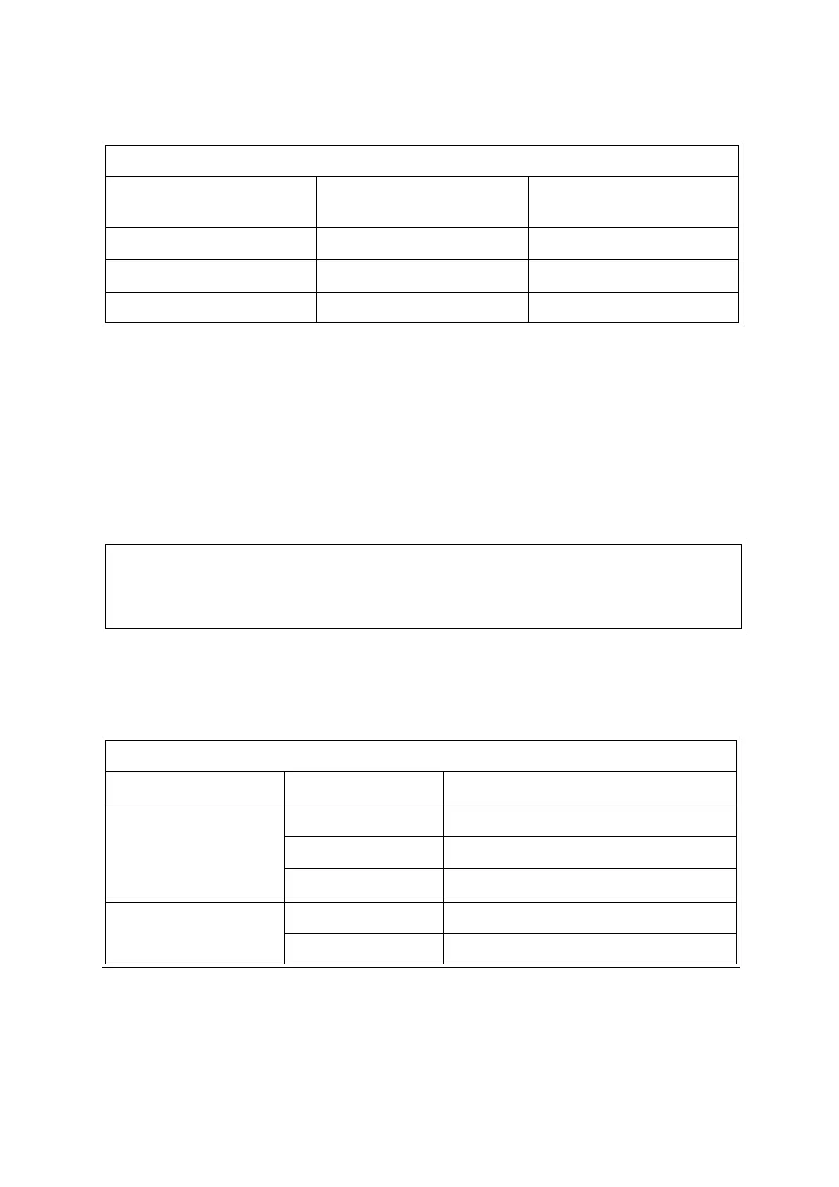
Table 3.4: External autocalibration truth table
Gas Required Relay Contacts for
Valve 1
Relay Contacts for
Valve 2
Sample Gas De-energised (OPEN) De-energised (OPEN)
Calibration gas 1 Energised (CLOSED) De-energised (OPEN)
Calibration gas 2 Energised (CLOSED) Energised (CLOSED)
NOTE
The RS232 and RS485 interfaces are non-isolated. When using the RS485 interface
with other non-isolated equipment, the difference in ground potentials must be no
greater than ±7V.
Table 3.5: Serial output connections PL6
Interface Terminal Function
RS232 2 Received data (RXD)
3 Transmitted data (TXD)
5 Signal common/ground
RS485 1 RS485- (B)
6 RS485+ (A)