1.3
1.3 Location of components
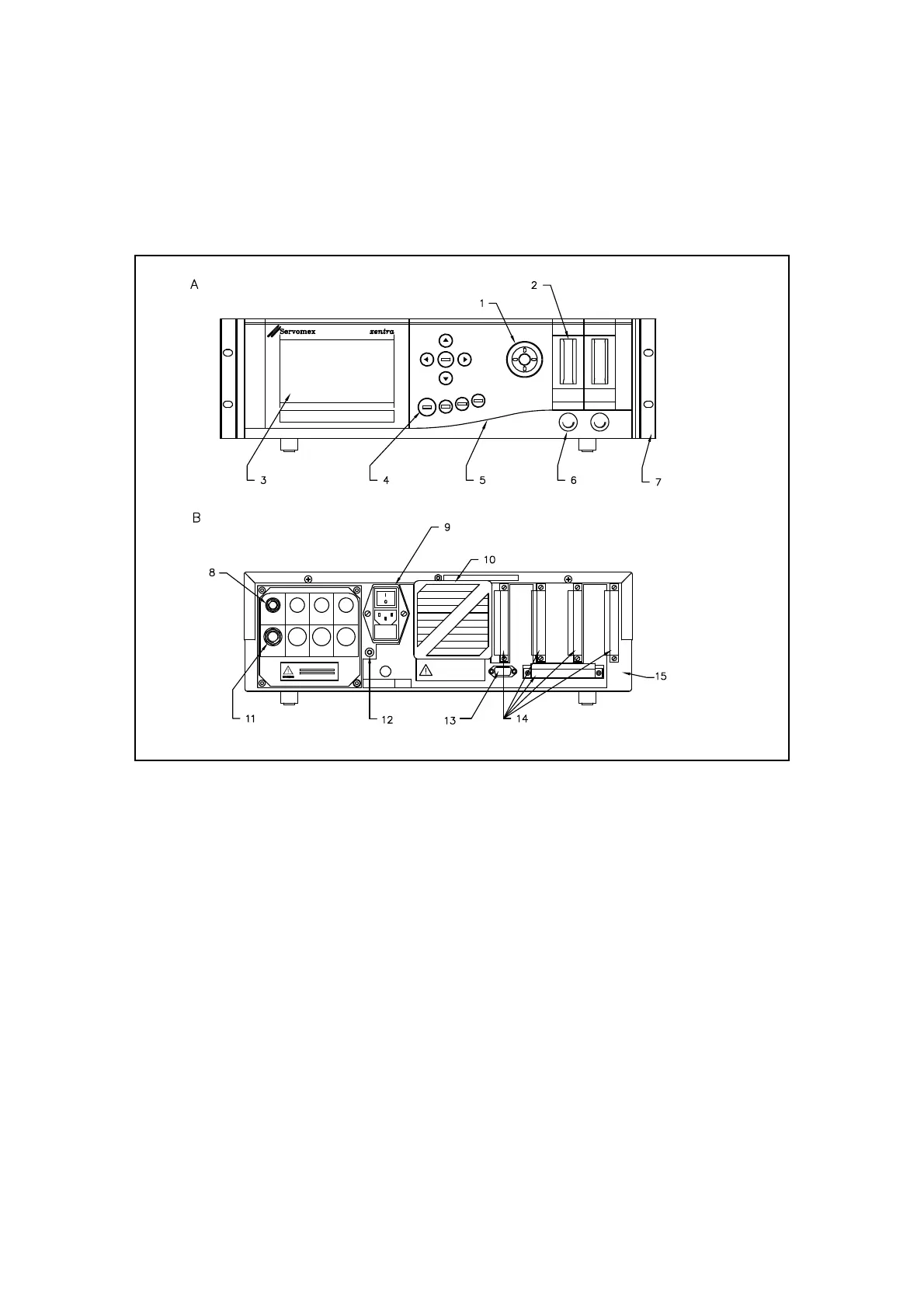
Figure 1.1 identifies the location of the key features of the analyser. Note that the identification
label (including serial number information) is located on the underside of the unit towards the
rear.
Figure 1.1: Key features of 4000 series analyser
Key A
B
1
2
3
4
5
6
7
FRONT VIEW
REAR VIEW
Sample filter (optional)
Flowmeter(s) (optional)
Display
Keypad
Display adjustment
Needle valve(s) (optional)
Rack mounting brackets
8
9
10
11
12
13
14
15
Sample inlet(s)
Mains power connector
Fan and filter
Sample outlet(s)
Functional earth
Serial output/Modbus port
Signal terminals
Screen