4.8
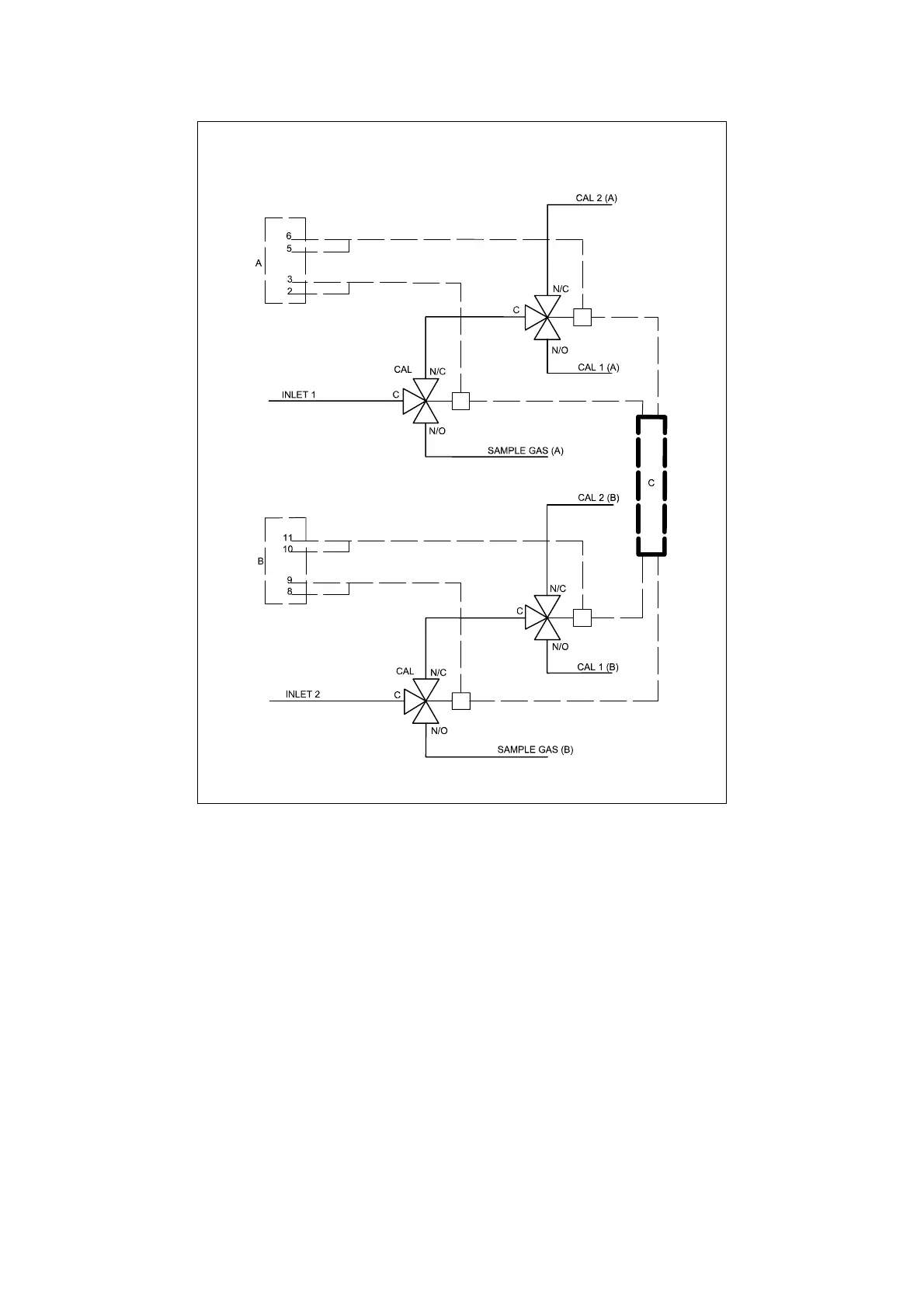
Figure 4.3: External autocalibration - parallel systems
Key: INLET 1, gas connection to analyser inlet 1
INLET 2, gas connection to analyser inlet 2
SAMPLE A, gas connection to sample gas 1
SAMPLE B, gas connection to sample gas 2
CAL1 (A), gas connection to calibration gas 1 associated with transducer 1
CAL2 (A), gas connection to calibration gas 2 associated with transducer 1
CAL1 (B), gas connection to calibration gas 1 associated with transducer 2
CAL2 (B), gas connection to calibration gas 2 associated with transducer 2
A, wiring to analyser option board, in this example PL8 (external autocal)
B, wiring to analyser option board, in this example PL1, 2, 3 or 4
C, external power supply
A similar arrangement may be used for up to four inlet ports.