3.3
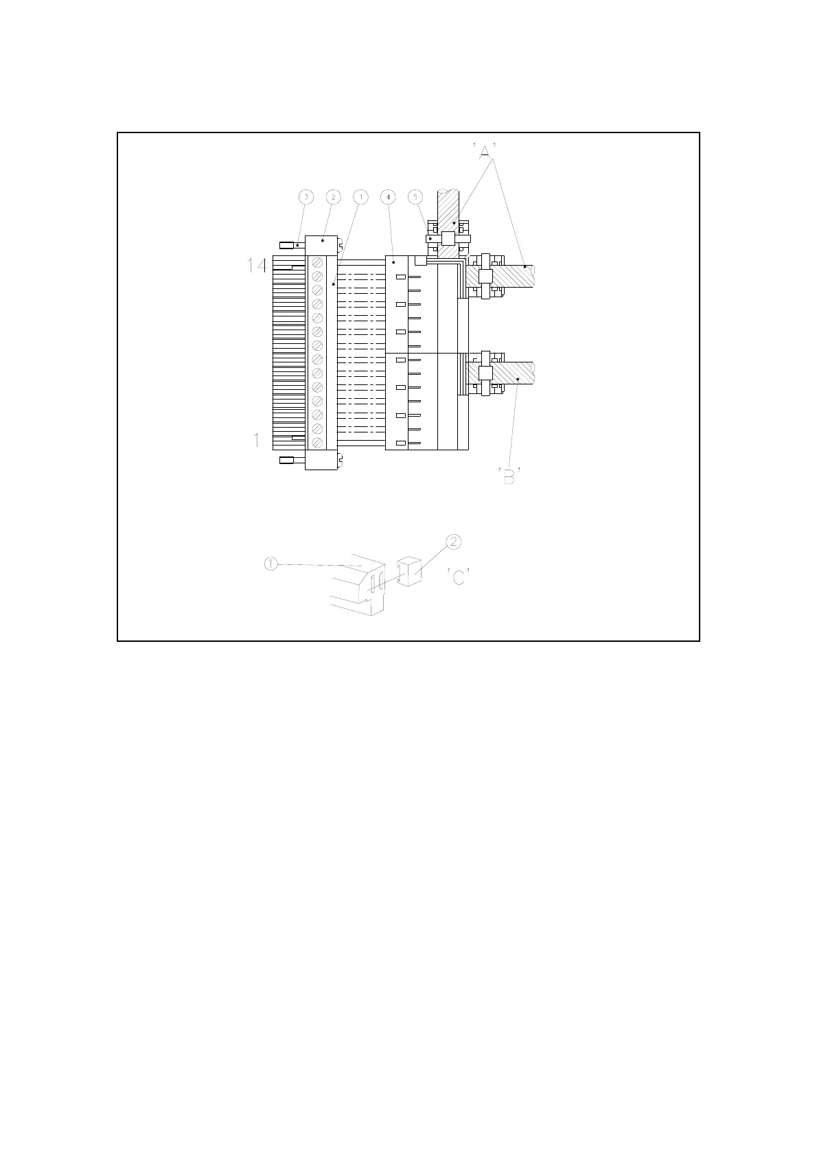
Figure 3.3: Signal socket assembly
For compliance with EMC standards connections to current outputs must use screened or
shielded cable, with either separately screened pairs or two pairs with an overall screen. The
screens ( or drain wire for foil screens ) must be terminated at pin 1 or pin 6 (both if separate
screened pairs are used).
All mA inputs and associated status lines (plug PL5) must use screened or shielded cables with
the screen or drain wire terminated at the terminals marked 'screen' on the connector.
Remaining signal inputs (plug PL5, terminals 11 to 14) must use screened or shielded cables
with the screen or drain wire terminated at the screen stud (M4) adjacent to PL5.
Key: 1
2
3
Screw terminal block
End block
Jacking screw
4
5
Cover
Cable tie
Notes A
B
C
Relay cabling may use either entry
Analogue output cabling
Mount item 2 by sliding them onto the dovetails in item 1