3.2
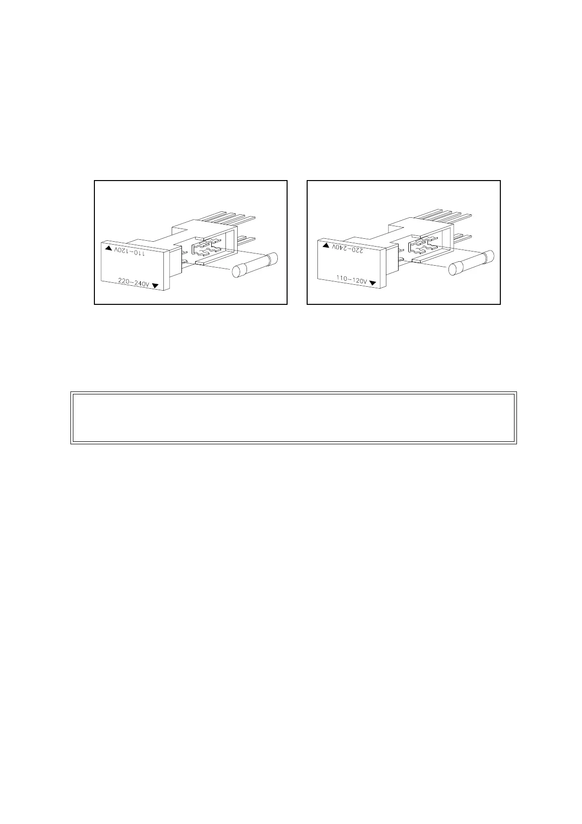
• Fit fuse F2 to the right hand side of the voltage selector according to the
voltage selected. Voltage selector position 220 to 240V operation fit fuse
T3.15A HBC to IEC 127 (Figure 3.1). Voltage selector position 110 to 120V
operation fit fuse T5.0A HBC to IEC 127 (Figure 3.2).
If a 20mm fuse is used then ensure that the fuse does not extend into the
spring clips provided for a 1 inch fuse.
3.2 Signal connections
It is recommended that the analyser is switched off while signal leads are being connected or
disconnected. Signal terminals are located on the rear of the analyser and are identified as
sockets PL1 to PL5. Two sockets PL1 and PL5 are always fitted, PL2, PL3 and PL4 sockets
are present only when the corresponding option cards are fitted. PL8 is located on the gland
plate when the autocal option is fitted.
A loose 14-way socket connector with accessories is provided to make connections to each
plug. The plugs and sockets are keyed so that the sockets may only be located in the correct
plug position. The loose socket covers have an identification number which corresponds to the
mating plug. Ensure that each socket is always fitted with the correct covers. The separate
covers on PL1 to PL4 provide segregation between current output and relay wiring. The
sockets and cover must always be fitted and secured, even when signals are not required.
Figure 3.3 shows the assembly of plugs PL1 to PL4 with segregated covers. The assembly for
plug PL5 is similar but with a single 14-way cover provided. Plug PL8 is similar but has only
7-ways.
The loose sockets have screw terminal connections. These will accept a flexible conductor
which has a cross sectional area in the range 20 AWG to 16 AWG, 0.5 to 1.5mm
2
or a solid
conductor which has a cross sectional area in the range 20 AWG to 14 AWG, 0.5 to 2.5mm
2
.
Solid conductors larger than 18 AWG, 1mm
2
are difficult to dress inside socket covers and are
therefore not recommended.
Figure 3.1: Position of F2 in voltage
selector for 220V to 240V operation
Figure 3.2: Position of F2 in voltage
selector for 110V to 120V operation
CAUTION
The current outputs must not be allowed to exceed 30vrms (42.4vpeak) or 60 volt DC
to earth when connected to associated equipment.