

T
Timothy OrtizAug 5, 2025
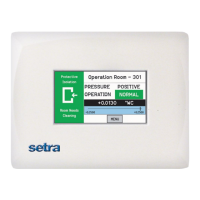
What to do if I lost the password for Setra Systems Measuring Instruments?
- JJohn NguyenAug 5, 2025
If you're having trouble with your Setra Systems Measuring Instruments and can't access the menus due to password protection, try using the default password, which is "351".