Signal wire size
Use wire between 0.5 mm² (20 AWG) and 1.5 mm² (16 AWG) for all signal wiring. Single twisted pair
cable is readily available in 0.5 mm² (20 AWG).
CANbus termination
If your system has more than one CAN node, connect the nodes in a ‘daisy chain’ arrangement and
terminate the connections of the two end nodes with a 120 resistor. If the end node is a Dragon8, link
pins 15 and 23 on the customer connector; a 120 resistor is built into the controller. If you have a
single node system, the termination resistor should be connected so that the bus operates correctly when
configuration tools are used.
Signal connections
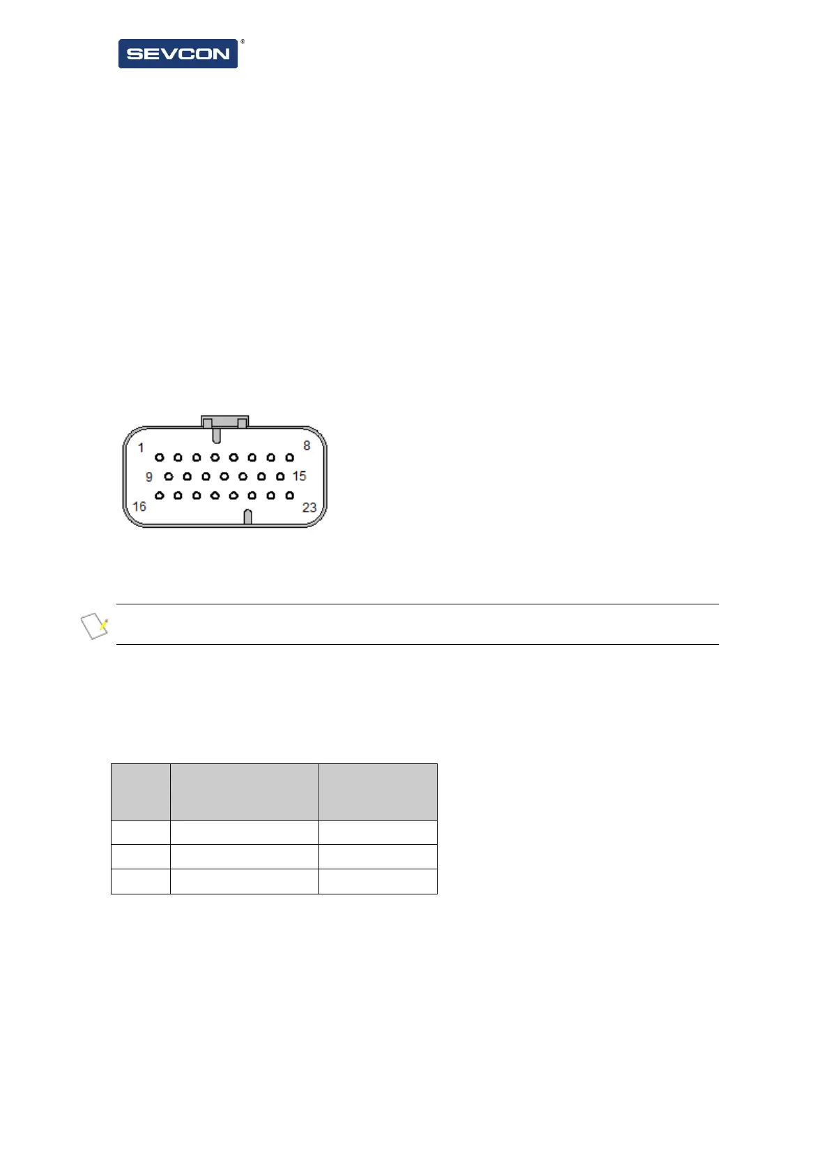
Signal connections are made to Dragon8 via a 23 way AMPSeal connector.
Figure 10 - AMPSeal Connector Pin Numbering
Pins are protected against short-circuits to the battery positive or negative terminals.
NOTE: Please see Tyco Application Specification 114-16016 and Instruction sheet 408-3229 before assembling
the AMPseal connector.
Inserting contacts into connector housing pierces the sealing diaphragm to make the seal to the wire. To
maintain IP rating, unused positions must be sealed with appropriate hardware (available from Tyco) if a
contact is inserted and then subsequently removed. It is recommended that Tyco strain relief 776464-1 is
used (especially for applications where the connector is less than fully populated) to reduce chance of
ingress through connector body.
Table 3 - Impedance at Digital Input Pins
* Type C digital inputs are coupled via a blocking diode and are pulled up to an internal 5V source via a
1kΩ resistor.
Configure the digital input switches as active-high (switched to Vb) or active-low (switched to battery
negative). Configuration applies to all dedicated digital input switches (1 to 3) i.e. they are all active-high
or all active-low. See section Digital inputs (page 52) for more details.