Discharge sequence after power down
Hazardous voltages will remain on the controller internally and on exposed power terminals for a
period of time after the main power connections have been removed.
Hazardous voltages may remain on the controller internally and on exposed power terminals after
the main battery power connections and keyswitch power supplies have been removed if the
controller is connected to a rotating permanent magnet motor.
Controller discharge profile
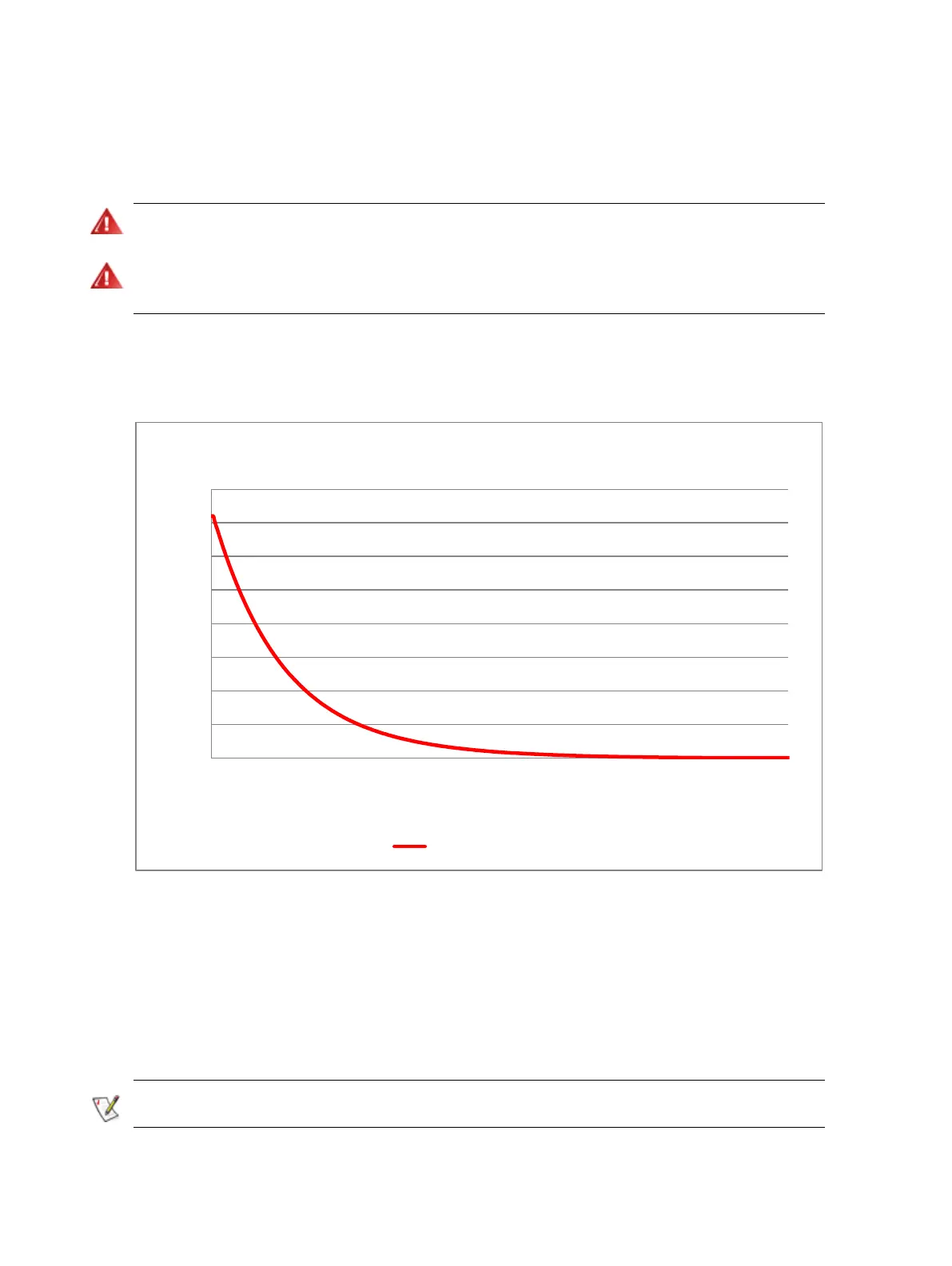
The following graph shows the standard controller discharge curve which should be observed.
Do not open the unit or work near exposed power terminals until the voltage has reduced to a safe level.
Figure 20 – Typical discharge curve for the Dragon8 controller
To determine the required time, note the time at which the “Voltage (maximum)” curve crosses the
horizontal gridline corresponding to the supply voltage. Then note the time at which it crosses the
horizontal gridline corresponding to the safe voltage level (normally considered to be 60V). The
difference between the two times is the safe discharge time period.
This information is for guidance only, and before any work is carried out on the high voltage
connections, it is essential the voltage is checked using a DVM and probes rated for at least 1000V
To achieve a shorter discharge time the vehicle system designer must ensure that a circuit is also incorporated to
discharge the Dragon8 capacitor bank when it is disconnected from the battery.