Introduction
Manual – ECC-DFC field bus controller
3. Introduction
3.1. The concept
The ECC-DFC fieldbus controller that is used for conveyor belt control is a series
of individual ECC-DFC modules that are connected to each other via Ethernet
cabling in order to provide a complete solution for the function of motor rollers in
conveyor systems. Each module can operate up to 2 ECR motor rollers and 2
photo sensors in order to control up to 2 conveyor belt zones.
Each ECC-DFC module also has practical interfaces to the upstream and down-
stream Ethernet network cabling.
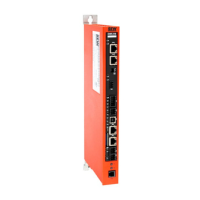
Figure 1 ECC-DFC fieldbus controller with 3 MODULES
The software of ECC-DFC modules can be easily configured in order to operate
several zones of linear conveyors with the ECShell engineering software. The
default settings of each ECC-DFC module can also be modified using ECShell in
order to adapt the function to specific applications.
3.1.1. System components
The typical components that are needed for a system with ECC-DFC fieldbus
control are listed in the following:
Modules of the ECC-DFC fieldbus controller
Motor rollers (1 – 2 per module)
Photo sensors (1 – 2 per module)
DC 24 V current supplies
3.2. Module properties
Each ECC-DFC module has the following properties:
Installed Ethernet switch
Modular M8 sockets for the photo sensors
Modular M8 connectors for the motor rollers
DC 24 V power connection with separate current supplies for logic and motors
Context-sensitive, multi-colored LED displays
Thermal protection and overcurrent protection for motor rollers
Automatic light/dark detection for the photo sensor inputs
Automatic PNP/NPN detection for the photo sensors
Proportional/integral (PI) motor roller speed control as an option
Four motor roller braking methods
Adjustable acceleration and deceleration time
Degree of protection IP54
 Loading...
