Connections for linear conveyors
Manual – ECC-DFC field bus controller
The module will now attempt to act as a two-zone controller, even though only
one motor roller is connected.
INFORMATION
These invalid configurations will not lead to the auto configuration function being
aborted. The user will notice only the occurrence of faulty operation and/or unex-
pected results.
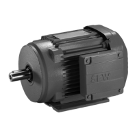
5.5. Definition of motor direction of rotation
The fieldbus control modules use two definitions of the motor direction of rotation:
clockwise (CW)
counter-clockwise (CCW)
The definition of the motor direction of rotation is based on the view of the motor
roller from the cable output side of the roller, as shown in figure 14.
Figure 14 motor direction of rotation

 Loading...