Introduction
Manual – ECC-DFC field bus controller
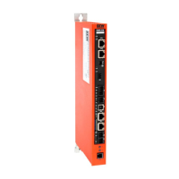
3.4. Overview of the hardware
ECC-DFC modules are designed such that they can be installed and integrated in
the side frame of the conveyor belt.
ECC-DFC modules can be used to control up to 2 motor roller zones of the con-
veyor belt. Each ECC-DFC has interfaces for 2 motor roller zones with the asso-
ciated 2 photo sensors and an upstream and downstream network. There are
also discrete connecting locations for setting up a complete control system for the
motor roller conveyor systems, which are divided up into zones.
Figure 2 Hardware overview
DC 24 V power connections with LED indicator
“Left motor” LED and “Right motor” LED motor status indicators
Left sensor and right sensor status LED indicators
Status LED indicator of the module
Power LED indicator of the module
Left motor connection, 4-pin M8 connector for motor roller connection
Right motor connection, 4-pin M8 connector for motor roller connection
Left sensor connection, M8 connection for zone photo sensor
Right sensor connection, M8 connection for zone photo sensor
Removable IP54 cover for the power wiring compartment
 Loading...
