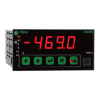
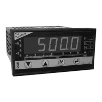
DGN175 Two-Colour Digital Panel Meters
The DGN175 series offers a comprehensive range of highly accurate programmable digital panel meters designed for industrial control rooms. These devices feature a two-colour 4-digit, 14mm high display with adjustable brightness, enabling clear visibility in various lighting conditions. They are capable of displaying, controlling, and transmitting data from a wide array of measurable magnitudes.
Function Description
The DGN175 meters are designed for versatile measurement and control applications. They can be configured via the front-face keyboard or through the SlimSET configuration software, which connects via a C1-µUSB cable (USB type A male to µUSB type B male). The software allows for reading measurements, modifying configurations, and saving/loading configurations as files.
Input Types:
The DGN175 series offers three main models:
- DGN175 U (Process Inputs): Features a bidirectional DC current or voltage input (±20mA, ±100mV, ±1V, ±10V, ±150V, ±300V). It supports measurable scale overrange from -10% to +10%, programmable scale factor, enlarging effect, square root extraction, special linearisation in 20 points, and supply for 2 or 3-wire sensors.
- DGN175 T (Temperature Input): Includes thermocouple inputs (J, K, B, R, S, T, E, N, L, W/G, W3/D, W5/C) and sensor inputs for Pt 100 Ω and Ni 100 Ω. Wiring options include 2, 3, or 4 wires, with 2-wire Pt100 measurement also supported.
- DGN175 M (Universal Input): Combines the inputs of the DGN175 U and T models, adding resistive sensor inputs (0-400 Ω and 0-10 KΩ) and potentiometer inputs (100 Ω to 10 KΩ).
Output Options (to be specified on order):
- Isolated Analogue Output (A): Available as active current output (A1), passive current output (A2), or voltage output (A3). Features a programmable scale ratio with enlarging effect.
- Relay Outputs (R or R4): Offers 2 or 4 relays with setpoint or window modes. Includes alarm recording, adjustable time delay, hysteresis for each setpoint, and alarm messages.
- Isolated Digital Output (N): Provides RS 485 2-wire communication using MODBUS-JBUS protocol.
- Logic Input (T - signal 24 VDC): Two isolated logic inputs with programmable functions such as display hold, decimal point movement, tare function, and Min/Max zero reset.
- Bargraph (B - 16 LEDs display): Allows for quick evaluation of measured value variations with a programmable scale factor.
Programming Features:
The device offers extensive programming capabilities through its main menu, including:
- Input Programming: Configuration of process signals, temperature sensors, resistive sensors, and potentiometers, including input ranges, units, and wiring types.
- Display Factor Programming: Setting decimal point position, display resolution, and display factors for down and up scales.
- Advanced Functions: Special linearisation (up to 20 points), square root extraction, cut-off value setting, and digital filtering for unsteady inputs.
- Analogue Output Programming: Configuration of output type (current/voltage), down/up scales, and limitation types (Std or SCALE).
- Relay Output Programming: Activation/deactivation, operating mode (setpoint/window), setpoint values, hysteresis, time delay, LED status, alarm recording, and alarm message display.
- RS485 Output Programming: Slave numbers, transmission speed, parity, transmission rank of bytes, and time delay.
- Logic Inputs Programming: Defining actions for logic input activation (no action, decimal point movement, Min/Max zero reset, display hold, tare function).
- Safeties Programming: Sensor break detection, fallback values for analogue outputs, and self-diagnosis error handling.
- Display Settings: Brightness levels for displays and LEDs, basic colour choice (Red/Green or Red/White), condition for colour switch (no switch, on alarm, on error), status of the last digit, and display of unsignificant zeros.
- Access Code Programming: Setting a 4-digit code to protect the programming menu and locking specific functions.
- Simulation Menu: Simulating input, display, or analogue output values for testing.
- Direct Functions Menu: Quick access to functions like Min/Max zero reset, direct input measure display, alarm recording reset, quick alarm setpoint programming, menu adjustment, tare function, and display brightness setting.
- Keyboard Sensitiveness Setting: Adjusting the keyboard response to Low, Middle, or High.
- ABOUT Menu: Displays information about the product, including appliance type, number, program version, installed options, and flash memory checksum.
Important Technical Specifications
Dimensions:
- Case: 96 x 48 x 119.4 mm (with terminals)
- Cut-out for panel mounting: 43 x 91.2 mm
- Weight: Not specified
Display:
- ±10,000 points (14 mm high digits)
- Electroluminescent red and green (or red and white)
- Alarm LEDs + 2 LEDs with programmable functions
Power Supply:
- Max. operating range: 20 to 250 VAC 50/60Hz and 20 to 250 VDC
- Consumption: 3 W max., 6 VA max.
Galvanic Isolation:
- 3 kV-50 Hz - 1 min between supply, inputs, analogue output, relay outputs, RS485 output and logic input.
- 1.5 Kv between analogue output and RS485.
Measure Performance:
- Standard sampling time: 100 ms
- Common mode rejection rate: 130 dB
- Serial mode rejection rate: 50 dB 50/60 Hz
- Zero drift compensation
Intrinsic Error:
- mA/mV/V inputs: < ±0.05% of the Measure Range (MR)
- Thermocouple inputs: < ±0.1% of the MR, or 30µV typical (60µV max.)
- Pt100/Ni100/Resistive sensors: < ±0.1% of the MR
Input Impedance:
- mA inputs: Drop 0.9V max.
- V inputs: > 1 MΩ
- Current (Pt100/Ni100/Resistive): 250µA
- Max. current (Resistive): 250µA
- Max. voltage (Potentiometer): 100mV
Sensor Break Detection:
- mA input: if down scale ≥ 3.5 mA
- Other inputs: a 12 µA pulsed current allows the detection of line or sensor break.
CJC Efficiency (Thermocouple):
- -20°C to 60°C
- Internal CJC: ± 1°C ± 0.03°C/°C
Analogue Output Specifications:
- Current: Direct or reversed 0-20mA, Load impedance ≤ Rc 600Ω
- Voltage: Direct or reversed 0-10V, Load impedance > Rc 5kΩ
Relay Output Specifications:
- 2 or 4 change-over relays
- Setpoint per relay, configurable on the whole MR.
- Hysteresis programmable.
- Time delay programmable from 0 to 999.9 sec.
- 8A/250 VAC on resistive load.
Digital Communications:
- Isolated RS485, Protocol MODBUS/JBUS (EIA RS485).
Environmental Conditions:
- Operating temperature: -20 to 60°C
- Storage temperature: -20 to 70°C
- Pollution degree 2 and voltage surge category II or better.
- Max. altitude: 2000m.
Compliance with Standards:
- Directive LV 2014/35/UE: EN 61010-1
- Directive EMC 2014/30/UE: EN 61326-1
- Directive ROHS 2011/65/UE
Usage Features
User Interface:
The DGN175 features a clear, two-colour display and a 4-key front panel for intuitive navigation and programming. The display can show minimum/maximum values, direct input measures, and alarm messages. The keyboard can be locked to prevent accidental changes, indicated by an LED.
Programming Modes:
- Reading Mode: Allows access to menus without an access code, but without the ability to modify configurations.
- Programming Mode: Requires a 4-digit access code (default 0000) to modify settings. The instrument automatically reverts to measure mode with the previous configuration if no key is pressed for 1 minute.
Direct Functions:
Several functions are accessible directly from the measure display by pressing specific key combinations, such as zero reset for Min/Max values, direct input measure display, zero reset for alarm recordings, quick alarm setpoint programming, menu adjustment, and tare function.
Display Calibration (Menu Adjustment):
This feature allows for precise calibration of the display value against the physical value present on the input. For process, resistance, or potentiometer inputs, it readjusts the scale factor and display factor. For temperature inputs, it can set an offset or correct both slope and offset if two settings are performed.
Tare Function:
The tare function allows recording a displayed value as tare, which can then be cleared to zero the measurement.
Error Messages:
The device provides various error messages (e.g., "2000" for overrange, "OPEN" for sensor break, "Err 1" for value out of range, "OL" for displayable value overload, "Er" for self-diagnosis error) to assist in troubleshooting. Self-diagnosis errors are coded (e.g., Err. 1 for programming error, Err. 4 for offset error, Err. 8 for calibration error, Err. 32 for CJC error, Err. 64 for electrical overstepping).
Maintenance Features
Configuration Software (SlimSET):
The SlimSET software simplifies configuration management. It allows users to:
- Read measures and modify digital panel meter configurations.
- Save configurations as files on disk.
- Consult, modify, duplicate, or load configurations into the device.
- Create configuration files with or without a connected device.
- Print all configuration files.
Self-Diagnosis:
The DGN175 continuously monitors its components for drifts. The self-diagnosis system warns the user of abnormal increases in drifts before they can lead to false measurements, ensuring reliability.
Warranty:
The appliance is guaranteed for 1 year against design or manufacturing defects under normal operating conditions. Processing not under warranty requires acceptance of a repair estimate. Products are returned at the customer's charge and restored after processing. If no written agreement on the repair estimate is reached within 30 days, the products will not be kept. Complete warranty terms and details are available upon request.