AR-M256/M257/M258/M316/M317/M318/5625/5631 ADJUSTMENTS, SETTING 7 - 5
<Adjustment specification>
(6) Main scanning direction (FR direction) distortion
balance adjustment
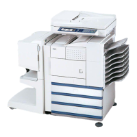
1) Remove the OC glass, the right cabinet and the upper right side
cover.
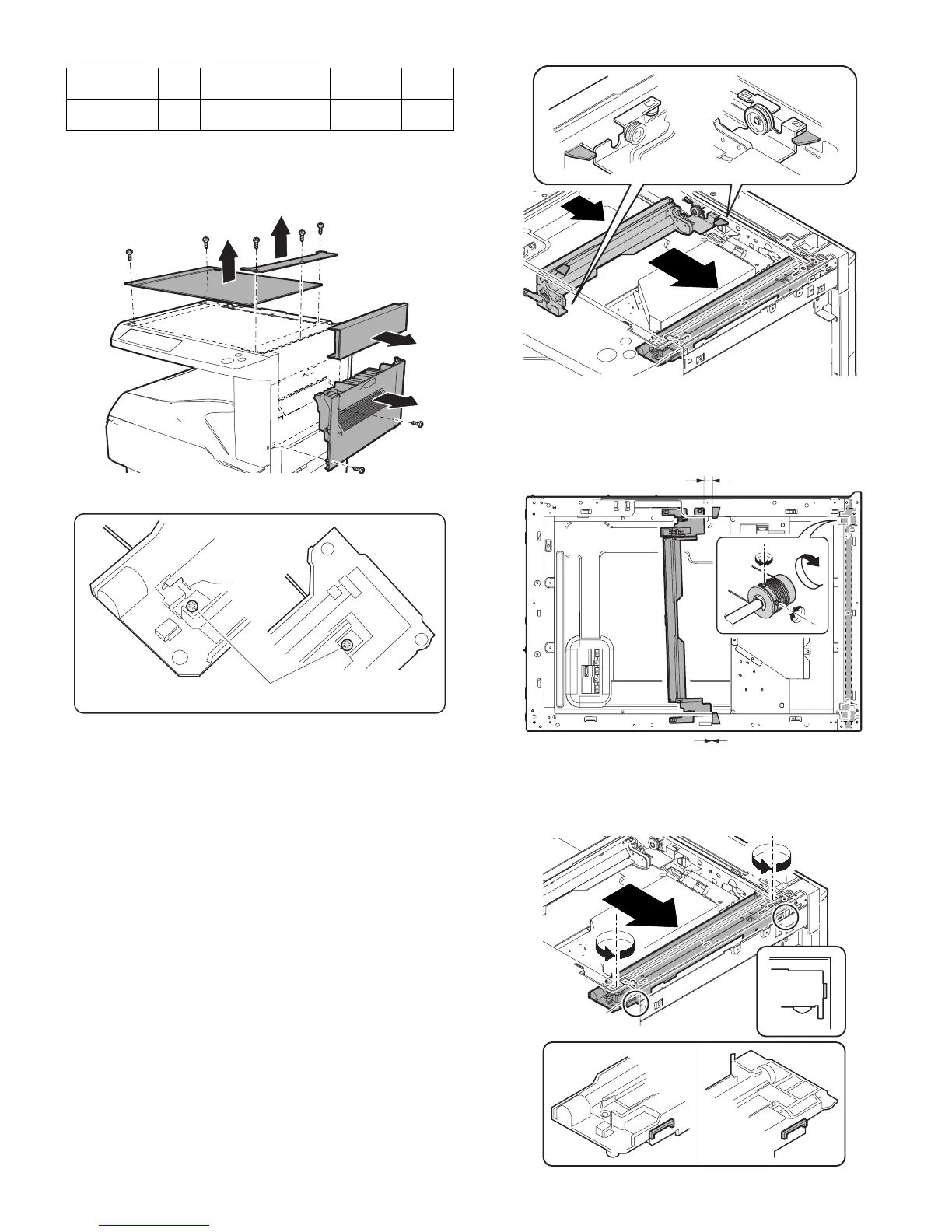
2) Loosen the copy lamp unit wire fixing screw.
3) Manually turn the mirror base drive pulley and bring No. 2/3 mirror
base unit into contact with the positioning plate.
At that time, if the front frame side and the rear frame side of No. 2/
3 mirror base unit are brought into contact with the positioning
plate at the same time, the mirror base unit parallelism is proper.
If one of them is in contact with the positioning plate, perform the
adjustment of 4).
4) Loosen the set screw of the scanner drive pulley which is not in
contact with No. 2/3 mirror base unit positioning plate.
5) Without moving the scanner drive pulley shaft, manually turn the
scanner drive pulley until the positioning plate is brought into con-
tact with No. 2/3 mirror base unit, then fix the scanner drive pulley.
6) Put No. 2/3 mirror base unit on the positioning plate again, push
the projections on the front frame side and the rear frame side of
the copy lamp unit to the corner frame, and tighten the wire fixing
screw.
Adjustment
mode
SIM Set value
Spec
value
Setting
range
Left edge void 50-1
-8
1 step: 0.127mm
shift
0.5 – 4mm 1 – 99
Wire fixing screw