AR-M256/M257/M258/M316/M317/M318/5625/5631 ADJUSTMENTS, SETTING 7 - 7
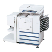
3) Measure the distances (La, Lb, Lc, Ld) at the four corners as
shown below.
When La = Lb and Lc = Ld, no need to perform the procedures 4)
and 5).
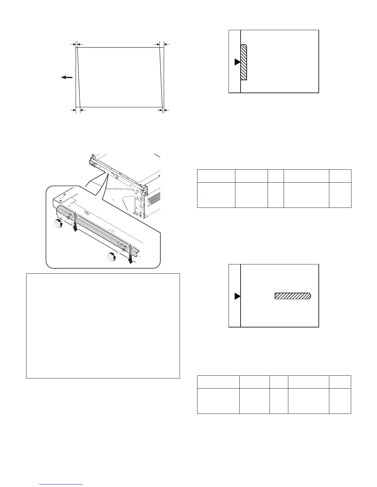
4) Move the mirror base B rail position up and down (in the arrow
direction) to adjust.
<Adjustment specification>
La = Lb, Lc = Ld
5) After completion of adjustment, manually turn the mirror base drive
pulley, scan the mirror base A and mirror base B fully, and check
that the mirror bases are not in contact with each other.
∗ If the mirror base rail is moved extremely, the mirror base may be in
contact with the frame or the original glass. Be careful to avoid this.
(9) Main scanning direction (FR direction) magnification
ratio adjustment (SIM 48-1)
Note: Before performing this adjustment, be sure to check that the
CCD unit is properly installed.
1) Put a scale on the original table as shown below.
2) Execute SIM 48-1.
3) After warm-up, shading is performed and the current set value of
the main scanning direction magnification ratio is displayed on the
display section in 2 digits.
4) Manual correction mode (SIM48-1-1)
Enter the set value and press the start key.
The correction value is stored and a copy is made.
<Adjustment specification>
Note: A judgment must be made with 200mm width, and must not be
made with 100mm width.
(10) Sub scanning direction (scanning direction)
magnification ratio adjustment
(SIM 48-1-2, SIM 48-1-3)
a. OC mode in copying
Note: Execute the procedure after completion of SIM 48-1-1.
1) Put a scale on the original table as shown below, and make a nor-
mal (100%) copy.
2) Compare the scale image and the actual scale.
If necessary, perform the following adjustment procedures.
3) Execute SIM 48-1-2.
4) Enter the set value and press the start key.
The set value is stored and a copy is made.
<Adjustment specification>
b. RSPF mode in copying
Note: Before performing this adjustment, be sure to check that the
CCD unit is properly installed and that OC mode adjustment in
copying has been completed.
• When La > Lb
Shift the mirror base B rail upward by the half of the difference of
La–Lb.
• When La < Lb
Shift the mirror base B rail downward by the half of the difference
of Lb–La.
Example: When La = 12mm and Lb = 9mm, shift the mirror base
B rail upward by 1.5mm.
• When Lc >Ld
Shift the mirror base B rail downward by the half of the difference
of Lc–Ld.
• When Lc < Ld
When Lc < Ld, move the mirror base B on the paper feed side
upward.
∗ When moving the mirror base rail, hold the mirror base rail with
your hand.
La
Lb Ld
Lc
Paper exit
direction
Adjustment
mode
Spec value SIM Set value
Setting
range
Main scanning
direction
magnification
ratio
At normal:
±1.0%
48-
1-1
Add 1: 0.1%
increase
Reduce 1: 0.1%
decrease
1 – 99
Adjustment
mode
Spec value SIM Set value
Setting
range
Sub scanning
direction
magnification
ratio (OC mode)
At normal:
±1.0%
48-1-
2
Add 1:
0.05% increase
Reduce 1:
0.05% decrease
1 – 99