AR-M256/M257/M258/M316/M317/M318/5625/5631 SIMULATION 8 - 15
Operation/procedure
1. Touch the exposure mode to be changed.
The current set value is highlighted.
2. Enter the set value with the 10-key.
3. Press the [START] key.
Output is made with the entered value for 30sec, and the display
returns to the original state.
Min. unit: 25V increment
*1. The negative value of the set value corresponds to the grid high
output voltage.
*2. The set values can be selected from the above 12 patterns only.
*3. The selected pattern determines the grid high voltage and the grid
low voltage.
If, for example, the grid high voltage is set to –605V (pattern 1), the
grid low voltage is –505V.
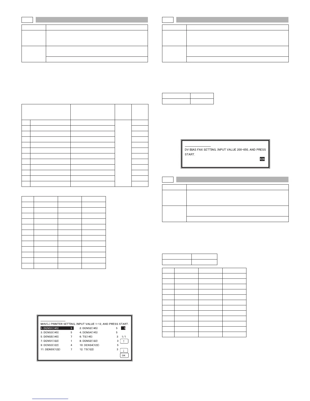
Operation/procedure
1. Enter the set value with the 10-key.
2. Press the [START] key.
Output is made with the entered value for 30sec. and the display
returns to the original state.
The minimum increment is 2V.
The result of (Set value-200) / 2 is stored in the EEPROM.
When reading a value from the EEPROM, the value of (EEP value ∗ 2
+200) is used as the set value.
Therefore, an even number must be entered. If not, the entered odd
number +1 is displayed after pressing [START] key.
Operation/procedure
1. Enter the set value with the 10-key.
2. Press the [START] key.
Output is made with the entered value for 30sec. and the display
returns to the original state.
Min. unit: 25V increment
8-12
Purpose Adjustment/Operation test/check
Function
(Purpose)
Used to check and adjust the operation of the main
charger grid voltage (low mode) in each printer mode
and the control circuit.
Section
Image process
(Photoconductor/Developing/Transfer/Cleaning)
Photo conductor
Item Content
Installa
tion
range
Default
1 DENS1 (145) Density 1 (145mm/s)
1-12
6
2 DENS2 (145) Density 2 (145mm/s) 6
3 DENS3 (145) Density 3 (145mm/s) 6
4 DENS4 (145) Density 4 (145mm/s) 7
5 DENS5 (145) Density 5 (145mm/s) 8
6 TS (145) Toner save (145mm/s) 4
7 DENS1 (122) Density 1 (122mm/s) 5
8 DENS2 (122) Density 2 (122mm/s) 5
9 DENS3 (122) Density 3 (122mm/s) 5
10 DENS4 (122) Density 4 (122mm/s) 6
11 DENS5 (122) Density 5 (122mm/s) 7
12 TS (122) Toner save (122mm/s) 3
NO. Set value Grid High Grid Low
1 6 –605V –505V
2 6 –605V –505V
3 6 –605V –505V
4 7 –630V –630V
5 8 –655V –555V
6 4 –555V –455V
7 5 –580V –455V
8 5 –580V –455V
9 5 –580V –455V
10 6 –605V –480V
11 7 –630V –505V
12 3 –530V –405V
SIMULATION 8-12
8-13
Purpose Adjustment/Operation test/check
Function
(Purpose)
Used to check and adjust the operation of the
developing bias voltage in FAX mode and the control
circuit.
Section
Image process
(Photoconductor/Developing/Transfer/Cleaning)
Developer/Toner hopper
Setting range 200-650
Default 426
8-14
Purpose Adjustment/Operation test/check
Function
(Purpose)
Used to check and adjust the operation of the main
charger grid voltage (high mode) in FAX mode and the
control circuit.
Section
Image process
(Photoconductor/Developing/Transfer/Cleaning)
Photo conductor
Setting range 1-12
Default 5
NO. Set value Grid High Grid Low
1 480 –480V –380V
2 505 –505V –405V
3 530 –530V –430V
4 555 –555V –455V
5 580 –580V –480V
6 605 –605V –505V
7 630 –630V –530V
8 655 –655V –555V
9 680 –680V –580V
10 705 –705V –605V
11 730 –730V –630V
12 755 –755V –655V
SIMULATION 8-13