MX-FN27, MX-PN14 ADJUSTMENTS 3 – 1
MX-FN27, MX-PN14
Service Manual
[3] ADJUSTMENTS
1. Punch Unit (MX-PN14)
A. Adjustments and settings item list
B. Details
ADJ 1 Punch unit, punch PWB
destination setting
1) When the punch PWB is replaced, the destination setting must
be performed.
2) SIM26-50 item J to set destination.
3) The relationship between the switches and the destinations is
shown in the table below.
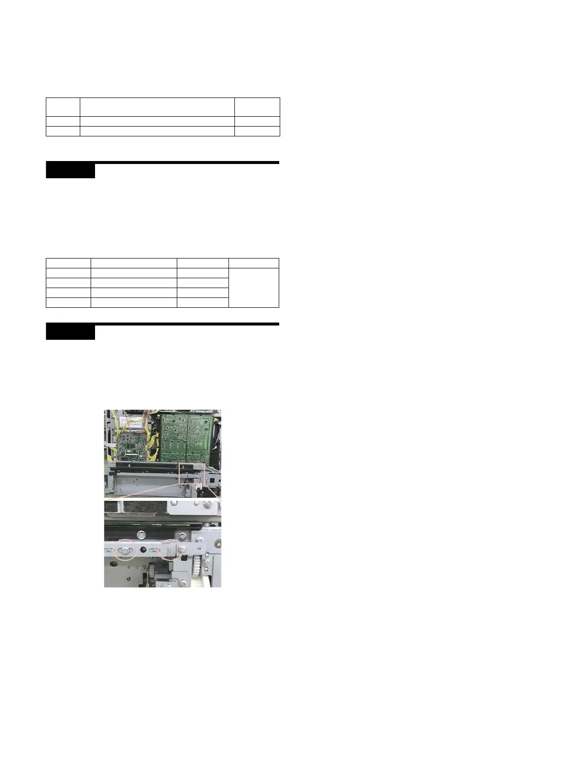
ADJ 2 Punch position adjustment
When the flapper solenoid is disassembled, an adjustment is
required when assembling.
1) Remove the Rear Cabinet.
2) Loosen the screw shown in the figure and adjust the position
by referring the scale on the plate.
JOB No. Adjustment and setting item
Simulation
to be used
ADJ 1 Punch unit, punch PWB destination setting –
ADJ 2 Punch position adjustment –
Model Kind of punching Setting value Default
MX-PN14A 2-hole 1
0
(Destination
is not set.)
MX-PN14B 2/3-hole 2
MX-PN14C 2/4 holes 3
MX-PN14D 4 holes (wide) 4