MX-M350/M450 N/U ADJUSTMENTS 8 - 5
When the set value is increased, the warp amount of paper is
increased. When the adjustment value is decreased, the warp
amount of paper is decreased.
<4> Self print lead edge adjustment
Items which must have been completed before this adjust-
ment.
• LSU right angle adjustment (If there is no distortion in self print,
the adjustment is not required.)
• Print off-center adjustment
• Resist amount adjustment
Items which must be executed after completion of this adjust-
ment.
• Front/rear and left/right void amount setting
• OC scan lead edge adjustment
• SPF scan lead edge adjustment
1) Execute SIM 50-5.
2) Set the lead edge void adjustment value (DENA) as specified
below.
(Standard set value) Paper lead edge void: 3.5mm (DENA: 35)
∗ Set the adjustment value of DENA to 35. (Enter 35 as the
adjustment value of DENA, and press [P] key.)
3) Check the lead edge void area on the self print pattern
(SIM67-1).
(Enter 1 and press [START] key.)
4) If the adjustment result is not satisfactory, perform the follow-
ing procedures.
∗ If the lead edge void area is not 3.5mm:
Change the adjustment value of RRCB and perform the
adjustment. (Change the adjustment value of RRCB and
press [START] key.)
(Shift for the adjustment value change: 0.1mm/step)
<Specification>
<5> Front/rear and left/right void amount setting
Items which must have been completed before this adjust-
ment.
• LSU right angle adjustment (If there is no distortion in self print,
the adjustment is not required.)
• Print off-center adjustment
• Resist amount adjustment
• Print lead edge adjustment
Items which must be executed after completion of this adjust-
ment.
• OC scan lead edge adjustment
• SPF scan lead edge adjustment
1) Execute SIM 50-1.
(Lead edge image loss/void area adjustment)
1) Set the lead edge image loss adjustment value (LEAD EDGE)
and the paper lead edge void adjustment value (DENA) as fol-
lows.
(Standard set value)
Lead edge image loss: 1.5mm (LEDA: 15)
Paper lead edge void: 3.5mm (DENA: 35)
∗ Set LEAD to 15. (Enter 15 as the adjustment value of LEAD,
and press [P] key.) (0.1mm/step)
∗ Set DENA to 35. (Enter 35 as the adjustment value of
DENA, and press [P] key.) (0.1mm/step)
2) Make a copy at the normal ratio (100%) and check the lead
edge void area and the image loss. (Enter 100 as the set value
of the copy magnification ratio (MAGNIFICATION), and press
[START] key.)
3) If the adjustment result is not satisfactory, perform the follow-
ing procedures.
∗ If the lead edge void are is not 3.5mm:
Change the adjustment value of RRCB and perform the
adjustment. (Change the adjustment value of RRCB and
press [START] key.) (1msec/step)
∗ If the lead edge image loss is not 1.5mm:
Change the adjustment value of RRCA and perform the
adjustment. (Change the adjustment value of RRCA and
press [START] key.)
(Shift for the adjustment value change: 0.2mm/step)
(Rear edge void area adjustment)
Adjust so that the rear edge void area is 3.5mm. (Change the
adjustment value of TRAIL EDGE, and press [START] key.)
(Front/rear frame direction image loss adjustment)
Set the adjustment value of SIDE to 20. (Enter 20 as the adjust-
ment value of SIDE, and press [P] key.)
When the adjustment value is changed, the image position is
shifted in the front/rear frame direction.
(Front/rear frame direction void area adjustment)
Adjust so that the total of the front/rear direction void areas is
7.0mm. (Change the adjustment values of FRONT/REAR, and
press [START] key.)
Front frame void area = 3.5mm Rear frame void area = 3.5mm
If, as shown above, the front and the rear void areas are not even,
use SIM 50-5 to adjust the image off-center position.
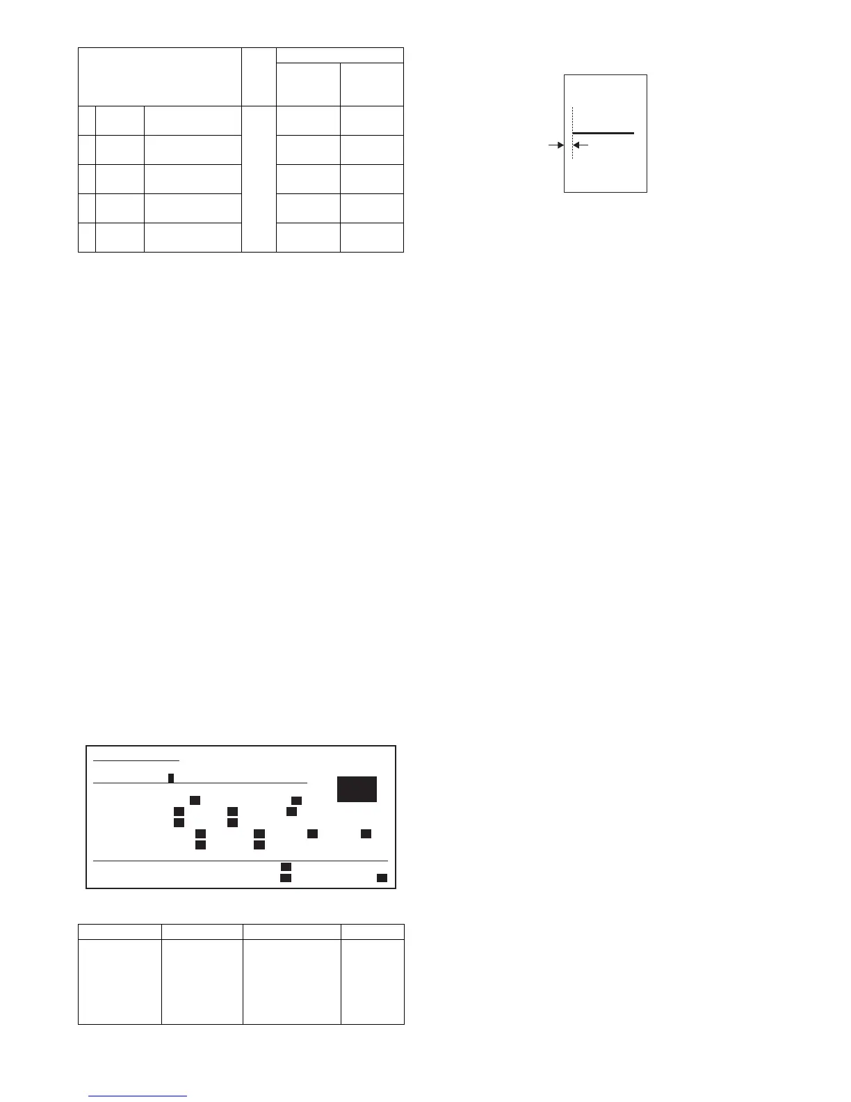
Item
Set
range
Default
MX-
M350U/
M350N
MX-
M450U/
M450N
2 TRAY1 Tray 1 resist
adjustment value
0 - 99 65 60
3 TRAY2 Tray 2 resist
adjustment value
55 50
4 DESK Desk resist
adjustment value
55 50
5 BPT Manual tray resist
adjustment value
60 55
6 ADU ADU resist
adjustment value
55 50
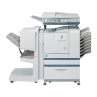
Set position Specification Set value
Self print lead
edge
adjustment
SIM 50-5
Print start
position A of
the output
pattern 1
A = 4.0mm or less
(Lead and tail
total: 8.0mm or
less)
Shift of
0.175mm
(35ppm) /
0.225mm
(45ppm) for
set value 1.
2
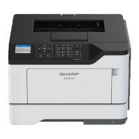
SIMULATION 50-5
LEAD EDGE ADJUSTMENT. SELECT 0-20, AND PRESS START.
0.TRAY SELECT 1 1.PRINT START
(ADJUSTMENT DATA)
LEAD EDGE: 2.RRCB 50 3.SIDE2 ADJ. 50
RESIST: 4.T1 50 5.T2 50 6.DESK 50
7.BPT 50 8.ADU 50
OFF CENTER: 9.T1 50 10.T2 50 11.T3 50 12.T4 50
13.BPT 50 14.ADU 50
(VOID SETTING) 15.LEAD_EDGE(DENA) 50
16.TRAIL_EDGE(DENB) 30 17.FRONT/REAR 30
A
[Output pattern]