MX-M350/M450 N/U MAINTENANCE AND DETAILS OF EACH SECTION 7 - 1
[7] MAINTENANCE AND DETAILS OF EACH SECTION
• Self print of set values
Use of SIM 22-6 allows to print the set values and the jam his-
tory of the machine.
These values must be printed before execution of maintenance
or disassembly procedures.
• When assembling, check that the flat cable and the harness
connectors are securely connected.
• When connecting the flat cable, be careful not to break the pins.
When installing the PWB unit and the memory module, use a
Ground Strap to prevent damage caused by electrical dis-
charge.
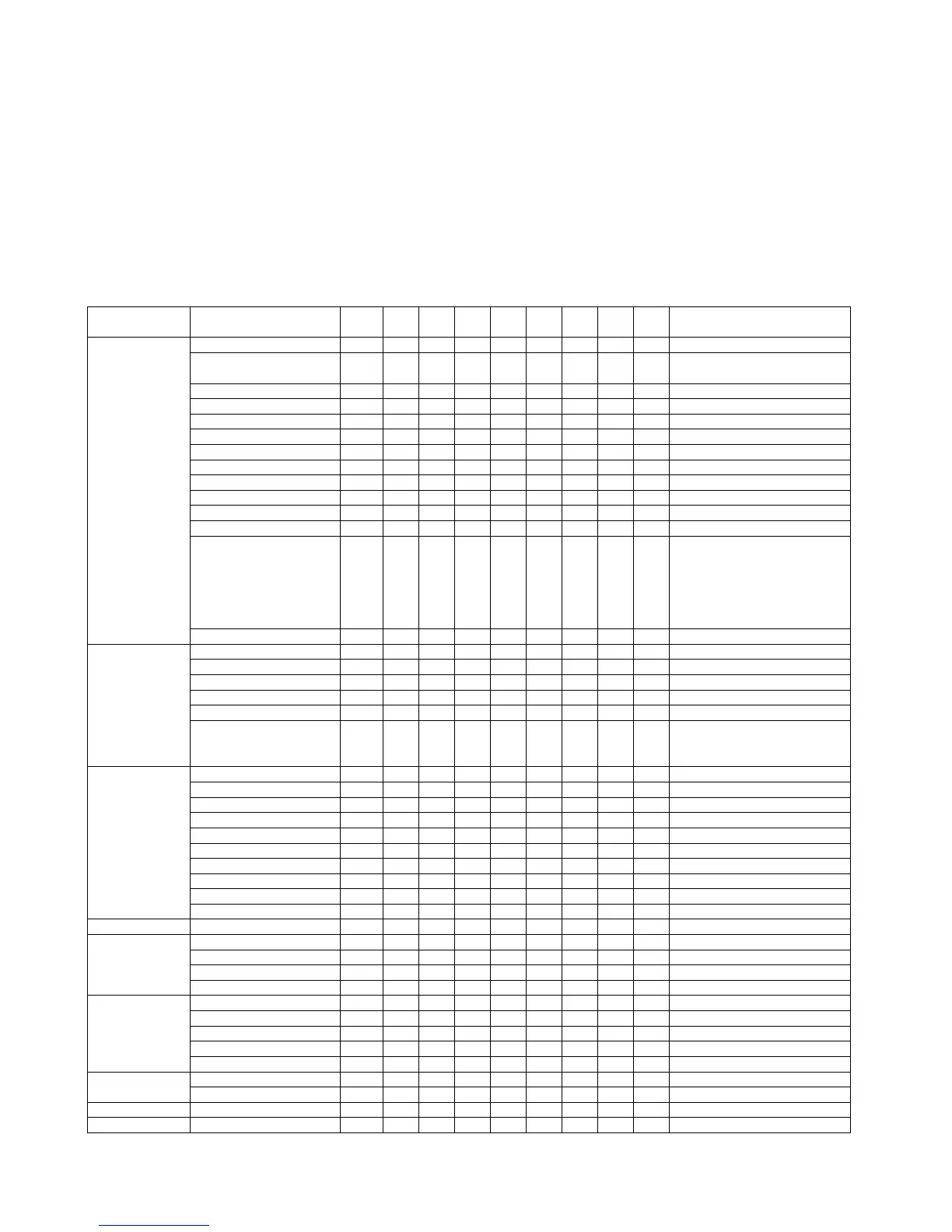
[Maintenance System Table]
1. Engine section
Maintenance cycle : 200K
✕ Check (Clean, replace, or adjust as necessary.) ❍ Clean ▲ Replace ∆ Adjust ✩ Lubricate ❏ Move position
Unit name Part name
When
calling
100K 200K 300K 400K 500K 600K 700K 800K Remark
Drum peripheral Drum ✕▲✕▲✕▲✕▲
Cleaner blade ✕▲✕▲✕▲✕▲Replace at 200K or 1 year.
P/G No.: [10]-49
Toner reception seal ✕▲✕▲✕▲✕▲P/G No.: [10]-42
Side molt F ✕▲✕▲✕▲✕▲P/G No.: [10]-33
Side molt R ✕▲✕▲✕▲✕▲P/G No.: [10]-37
Transfer roller ✕ ✕▲✕▲✕▲✕▲P/G No.: [5]-8
Discharge plate ✕ ✕▲✕▲✕▲✕▲P/G No.: [5]-2
TR bearing (F/R) ✕✕✕▲✕✕✕▲P/G No.: [5]-9, 18
Transfer roller collar ✕✕✕▲✕✕✕▲P/G No.: [5]-10
After-transfer star ring ✕✕✕✕✕✕✕✕P/G No.: [5]-19
TR gear ✕ ✕▲✕▲✕▲✕▲P/G No.: [5]-15
Drum separation pawl unit ✕▲✕▲✕▲✕▲P/G No.: [5]-501
MC unit ✕ ❍▲❍▲❍▲❍▲Includes the screen grid, the
charging plate, and the MC
cleaner.
❍: Charging plate cleaning by
the MC cleaner
P/G No.: [9]-901
Paper guide ❍ ❍❍❍❍❍❍❍❍
Developing
section
Developer ▲▲▲▲▲▲▲▲Supplied when installing
DV blade ✕▲✕▲✕▲✕▲P/G No.: [11]-55
DSD collar ❍❍❍❍❍❍❍❍
DV side seal F ✕▲✕▲✕▲✕▲P/G No.: [11]-38
DV side seal R ✕▲✕▲✕▲✕▲P/G No.: [11]-43
Toner cartridge ––––––––
Attached when installing./
750g, user replacement for every
35K.
Fusing section Upper heat roller ✕ ✕▲✕▲✕▲✕▲P/G No.: [7]-46
Lower heat roller ✕ ✕▲✕▲✕▲✕▲P/G No.: [7]-22
Upper separation pawl ❍ ❍▲❍▲❍▲❍▲P/G No.: [7]-3
Lower separation pawl ❍ ❍▲❍▲❍▲❍▲P/G No.: [7]-41
Thermistor ✕ ✕✕✕✕✕✕✕✕Clean and remove paper dust.
Upper heat roller gear ✕▲✕▲✕▲✕▲P/G No.: [7]-47
Paper guides ❍ ❍❍❍❍❍❍❍❍
Gears ✩✩✩✩✩✩✩✩
CL roller ✕ ✕▲✕▲✕▲✕▲P/G No.: [7]-52
CL roller bearing ✕ ✕▲✕▲✕▲✕▲P/G No.: [7]-53
Filters Ozone filter ▲▲▲▲▲▲▲▲P/G No.: [12]-2
Paper feed
section
Pick-up roller ✕ ✕✕✕✕✕✕✕✕Note 1
Paper feed roller ✕ ✕✕✕✕✕✕✕✕Note 1
Separation roller ✕ ✕✕✕✕✕✕✕✕Note 1
Torque limiter ✕ ✕✕✕✕✕✕✕✕Note 1
Transport section
Paper exit
reverse section
Resist roller ✕ ❍❍❍❍❍❍❍❍
Transport rollers ✕ ❍❍❍❍❍❍❍❍
Transport paper guides ❍ ❍❍❍❍❍❍❍❍
Paper dust remover unit ❍ ❍▲❍▲❍▲❍▲P/G No.: [14]-51
Optical reflection sensor ❍ ❍❍❍❍❍❍❍❍PS roller unit section
Drive section Gears (Specified position) ✕ ✩✩✩✩✩✩✩✩
Belts ✕ ✕✕✕✕✕✕✕✕
Image quality ✕ ✕✕✕✕✕✕✕✕
Other Sensors ✕✕✕✕✕✕✕✕Clean with air.
Note 1: Replacement reference:Use the counter value of each paper feed port as the replacement reference.
Paper feed roller/Separation pad/Torque limiter section (Include Desk, Multi purpose): 100K or 1 year