Introduction
Page / 3
Designs and specifications are subject to change without notice.
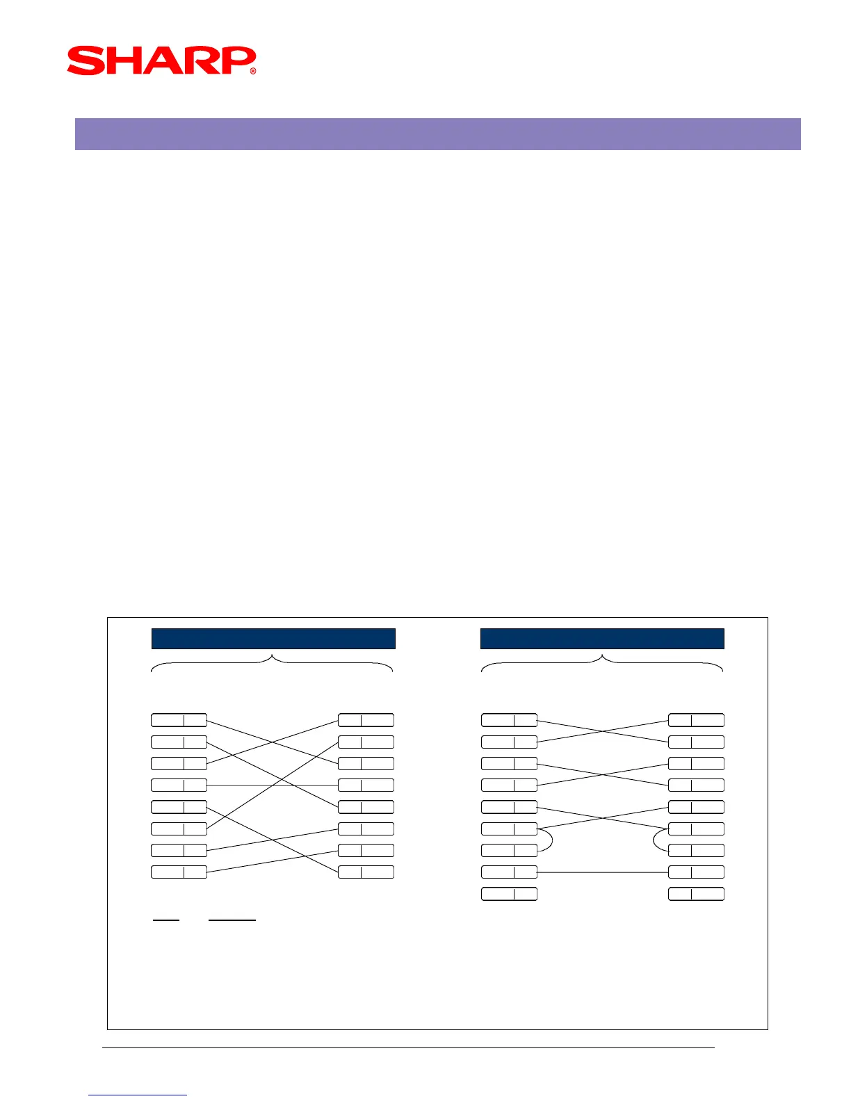
9 PIN D-SUB 9 PIN D-SUB 9 PIN D-SUB
RTS 1 3 SD SD 3 3 SD
DTR 2 2 RD RD 2 2 RD
SD 3 7 RTS RTS 7 7 RTS
DCD 4 1 DCD DCD 1 1 DCD
SG 5 4 DTR DTR 4 4 DTR
RD 6 6 DSR DSR 6 6 DSR
DTR 7 8 CTS CTS 8 8 CTS
CTS 8 5 SG SG 5 5 SG
CI 9 9 CI
Signal
Description
SD : Transmitt Data
RD : Receive Data
DTR : Data Terminal Ready
DSR : Data Set Ready
RTS : Request to Send
DCD : Data Carrier Detector
CTS : Clear to Send
SG : Signal Ground
RJ45 Modular
( Not used )
PCECR <-- to Conversion Cableto Extenion Cable -->
Extension CableUP-700 Modular Conversion Cable
The SIO function is used to download the logo image to the UP-700 from the PC. Yjr SIO function is
dedicated to COMM-2 with connection via an RJ45 modular jack.
The below diagram represents the cable specifications required when connecting the UP-700 to a PC
when the Logo Image Data function is used.
1. Specifications:
(1) Conversion Cable: CAT-5, twisted pair , 24 AWG
(2) Connectors: RJ45 Modular, D-Sub 9 pin (male type) connector
(3) Extension Cable: Shielded, twisted pair , 24 AWG
(4) Connectors: D-Sub 9 pin (female type) connector
(5) Baud Rates: 115200, 38400, 19200, 9600, 4800, 2400, 1200
2. Pin Outs:
The SIO function is used to download the logo image to the UP-700 from the PC. The SIO
function is dedicated to COMM-2 with connection via an RJ45 modular jack.
The recommended connection between the UP-700 and a PC for usage of the Logo utility is via
two cables which are outlined below;
Please refer to (fig. 1) below for the connection pin out diagram.
CABLE SPECIFICATIONS
(FIG.1)