Shure Incorporated
27/29
•
•
•
•
Network Addressing Capability
DHCP or Manual IP address
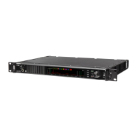
DC Module Specifications
DC Input Voltage Range
10.9 - 16V
Maximum DC Input Current
5.5 A
Protection Modes
Reverse Polarity, Over Voltage
Connector Type
4-pin XLR (male)
The shell of the DC inlet XLR connector is connected to Chassis Ground.
Recommended Cable Gauge
6 feet or less 18 AWG (1 mm )
7 to 15 feet 16 AWG (1.5 mm )
16 to 25 feet 14 AWG (2.5 mm )
Important: Total cable length should not exceed 25 feet.
Information to the user
This equipment has been tested and found to comply with the limits for a Class B digital device, pursuant to part 15 of the FCC
Rules. This equipment generates, uses, and can radiate radio frequency energy and, if not installed and used in accordance
with the manufacturer's instruction manual, may cause interference with radio and television reception.
Notice: The FCC regulations provide that changes or modifications not expressly approved by Shure Incorporated could void
your authority to operate this equipment.
Theselimitsaredesignedtoprovidereasonableprotectionagainstharmfulinterferenceinaresidentialinstallation.Thisequip
mentgenerates,uses,andcanradiateradiofrequencyenergyand,ifnotinstalledandusedinaccordancewiththeinstruc
tions, may cause harmful interference to radio communications. However, there is no guarantee that interference will not occur
inaparticularinstallation.Ifthisequipmentdoescauseharmfulinterferencetoradioortelevisionreception,whichcanbede
termined by turning the equipment off and on, the user is encouraged to try to correct the interference by one or more of the
following measures:
Reorient or relocate the receiving antenna.
Increase the separation between the equipment and the receiver.
Connect the equipment to an outlet on a circuit different from that to which the receiver is connected.
Consult the dealer or an experienced radio/TV technician for help.
2
2
2