For acoustical-electrified instruments such as classic
or folk guitars with pickups and preamplifier outputs, or
pianos with pickups and preamplifier outputs, either place
the microphone as described above, or connect the pickup
to an AUX. LEVEL lnput Jack (32) on the Console. If the
cable from the instrument to the Console is greater than
6.lm (20 ft.), use a line matching transformer as described
under High-Impedance Microphones (Page 11). This trans-
former also allows the instrument to be connected to chan-
nels 1-6. Adjust the Console INPUT
ATTEN Control (14) for
the channel in use to provide the desired sound level with
the channel Volume Control (1) set at about mid-scale.
To use a preamplifier auxiliary output with the Console
(instrument or tape recorder preamplifier, or hi-fi amplifier
tape monitor output jack, or headphone jack; never speaker
jacks), connect the preamplifier auxiliary output through
up to
3.05m (10 ft.) of cable to the high-impedance side of
a line matching transformer (Shure A95 Series) as shown
in Figure 7, Page 11. Connect the low-impedance side of the
transformer through a low-impedance microphone cable
[up to 305m (1000
ft.)] to a Console MICROPHONE LEVEL
lnput Jack (33). Adjust Console equalization controls for
optimum sound. Adjust the Console INPUT
ATTEN Control
(14) for the channel in use to provide the desired sound
level with the channel Volume Control (1) set at about
mid-
scale.
Fully electrified instruments may also be amplified using
a microphone in front of the instrument speaker, or the in-
strument output (not the speaker jack) may be fed directly
to an input jack as described above. It is important to note
that the tonal quality of fully electrified instruments is pri-
marily formed by the instrument amplifier and speaker; an
external microphone picking up the instrument speaker
output may very well provide a more desirable sound than
that obtained by direct connections.
The cable length restrictions applying to high-impedance
microphones also apply to most musical instruments (see
High-Impedance Microphones, Page 11).
TAPE RECORDING
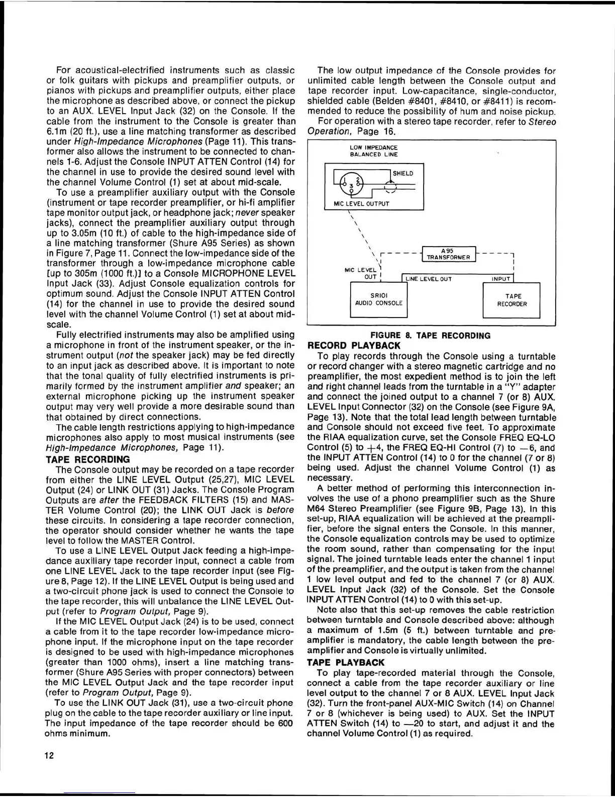
The Console output may be recorded on a tape recorder
from either the LlNE LEVEL Output
(25,27), MIC LEVEL
Output (24) or LlNK OUT (31) Jacks. The Console Program
Outputs are after the FEEDBACK FILTERS (15) and MAS-
TER Volume Control (20); the LlNK OUT Jack is before
these circuits. In considering a tape recorder connection,
the operator should consider whether he wants the tape
level to follow the MASTER Control.
To use a LlNE LEVEL Output Jack feeding a
high-impe-
dance auxiliary tape recorder input, connect a cable from
one LlNE LEVEL Jack to the tape recorder input (see Fig-
ure 8, Page 12). If the LINE LEVEL Output is being used and
a two-circuit phone jack is used to connect the Console to
the tape recorder, this will unbalance the LlNE LEVEL Out-
put (refer to Program Output, Page 9).
If the MIC LEVEL Output Jack (24) is to be used, connect
a cable from it to the tape recorder low-impedance micro-
phone input. If the microphone input on the tape recorder
is designed to be used with high-impedance microphones
(greater than
1000 ohms), insert a line matching trans-
former (Shure A95 Series with proper connectors) between
the MIC LEVEL Output Jack and the tape recorder input
(refer to Program Output, Page 9).
To use the LlNK OUT Jack
(31), use a two-circuit phone
plug on the cable to the tape recorder auxiliary or line input.
The input impedance of the tape recorder should be
600
ohms minimum.
The low output impedance of the Console provides for
unlimited cable length between the Console output and
tape recorder input. Low-capacitance, single-conductor,
shielded cable (Belden
#8401, #8410, or #8411) is recom-
mended to reduce the possibility of hum and noise pickup.
For operation with a stereo tape recorder, refer to Stereo
Operation, Page 16.
LOW IMPEDANCE
BALANCED LlNE
SHIELD
MIC LEVEL OUTPUT
\
\
\
\
\
TRANSFORMER
SRlOl
AUDIO CONSOLE RECORDER
FIGURE
8.
TAPE
RECORDING
RECORD PLAYBACK
To play records through the Console using a turntable
or record changer with a stereo magnetic cartridge and no
preamplifier, the most expedient method is to join the left
and right channel leads from the turntable in a
"Y"
adapter
and connect the joined output to a channel 7 (or 8) AUX.
LEVEL lnput Connector (32) on the Console (see Figure
9A,
Page 13). Note that the total lead length between turntable
and Console should not exceed five feet. To approximate
the RlAA equalization curve, set the Console FREQ EQ-LO
Control (5) to +4, the FREQ EQ-HI Control (7) to -6, and
the INPUT
ATTEN Control (14) to
0
for the channel (7 or 8)
being used. Adjust the channel Volume Control (1) as
necessary.
A better method of performing this interconnection in-
volves the use of a phono preamplifier such as the Shure
M64 Stereo Preamplifier (see Figure
96, Page 13). In this
set-up, RlAA equalization will be achieved at the preampli-
fier, before the signal enters the Console. In this manner,
the Console equalization controls may be used to optimize
the room sound, rather than compensating for the input
signal. The joined turntable leads enter the channel 1 input
of the preamplifier, and the output is taken from the channel
1 low level output and fed to the channel 7 (or 8) AUX.
LEVEL lnput Jack (32) of the Console. Set the Console
INPUT
ATTEN Control (14) to
0
with this set-up.
Note also that this set-up removes the cable restriction
between turntable and Console described above: although
a maximum of
1.5m
(5
ft.) between turntable and pre-
amplifier is mandatory, the cable length between the pre-
amplifier and Console is virtually unlimited.
TAPE PLAY BACK
To play tape-recorded material through the Console,
connect a cable from the tape recorder auxiliary or line
level output to the channel
7
or 8 AUX. LEVEL lnput Jack
(32). Turn the front-panel AUX-MIC Switch (14) on Channel
7 or 8 (whichever is being used) to AUX. Set the INPUT
ATTEN Switch (14) to -20 to start, and adjust it and the
channel Volume Control
(1) as required.
 Loading...