POTENTIOMETERS
RIA-RBA, R16A SLIDE ACTUATOR
SYNCHRONIZING
\
/
POTENTIOMETERS APPROXIMATELY
RIB-R88, R16B 1/16 IN. PLAY
LOWER
BEARING
ASSEMBLY
'-SETSCREW
\LOWER
PULLEY
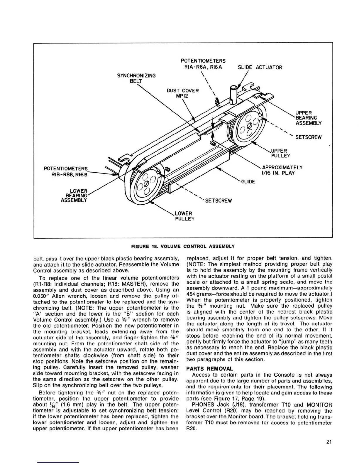
FIGURE
18.
VOLUME CONTROL ASSEMBLY
belt, pass it over the upper black plastic bearing assembly,
and attach it to the slide actuator. Reassemble the Volume
Control assembly as described above.
To replace one of the linear volume potentiometers
(Rl-R8: individual channels; R16: MASTER), remove the
assembly and dust cover as described above. Using an
0.050" Allen wrench, loosen and remove the pulley at-
tached to the potentiometer to be replaced and the syn-
chronizing belt. (NOTE: The upper potentiometer is the
"A" section and the lower is the
"B"
section for each
Volume Control assembly.) Use a
3/8" wrench to remove
the old potentiometer. Position the new potentiometer in
the mounting bracket, leads extending away from the
actuator side of the assembly, and finger-tighten the
3/e"
mounting nut. From the potentiometer shaft side of the
assembly and with the actuator upward, rotate both po-
tentiometer shafts clockwise (from shaft side) to their
stop positions. Note the setscrew position on the remain-
ing pulley. Carefully insert the removed pulley, washer
side toward mounting bracket, with the setscrew facing in
the same direction as the setscrew on the other pulley.
Slip on the synchronizing belt over the two pulleys.
Before tightening the
%I' nut on the replaced poten-
tiometer, position the upper potentiometer to provide
about
%,'I
(1.6 mm) play in the belt. The upper poten-
tiometer is adjustable to set synchronizing belt tension:
if the lower potentiometer has been replaced, tighten the
lower potentiometer and loosen, adjust and tighten the
upper potentiometer. If the upper potentiometer has been
replaced, adjust it for proper belt tension, and tighten.
(NOTE: The simplest method providing proper belt play
is to hold the assembly by the mounting frame vertically
with the actuator resting on the platform of a small postal
scale or attached to a small spring scale, and move the
assembly downward. A 1 pound maximum-approximately
454
grams-force should be required to move the actuator.)
When the potentiometer is properly positioned, tighten
the
3/s"
mounting nut. Make sure the replaced pulley
is aligned with the center of the nearest black plastic
bearing assembly and tighten the pulley setscrews. Move
the actuator along the length of its travel. The actuator
should move smoothly from one end to the other. If it
stops before reaching the end of its normal movement,
gently but firmly force the actuator to "jump" as many teeth
as necessary to reach the end. Replace the black plastic
dust cover and the entire assembly as described in the first
two paragraphs of this section.
PARTS REMOVAL
Access to certain parts in the Console is not always
apparent due to the large number of parts and assemblies,
and the requirements for their placement. The following
information is given to help locate and gain access to these
parts (see Figure 17, Page 19).
PHONES Jack
(J18), transformer TI0 and MONITOR
Level Control (R20) may be reached by removing the
bracket over the Monitor board. The bracket holding trans-
former
TI0 must be removed for access to potentiometer
R20.
 Loading...