SR101
Series
2
Audio Console
NOTES TO
CIRCUIT DIAGRAM
GENERAL
distorted, low or not present, apply an input signal as de-
Shure part numbers are not shown in the Parts List
scribed under
Ac
Voltage Measurements below, and deter-
accompanying the Circuit Diagram (Figure 31, Page 44)
mine that the input and output voltage to each board
if parts are readily available through local electronics parts
assembly is correct. If an incorrect ac voltage is found
suppliers. In these instances, the Circuit Diagram shows
at any board output, perform
Dc
Voltage Measurements
only the reference designation and value of the standard
on that board as described below to isolate the problem
parts. area.
All capacitor values are shown in microfarads unless
otherwise designated. All non-electrolytic capacitors are
100 working volts dc or more unless otherwise specified.
Electrolytic capacitors are shown in microfarads
x
volts.
All resistor values are shown in ohms (k
=
1000). Re-
sistors are
10% tolerance unless otherwise specified. Re-
sistors are
%-watt unless otherwise specified.
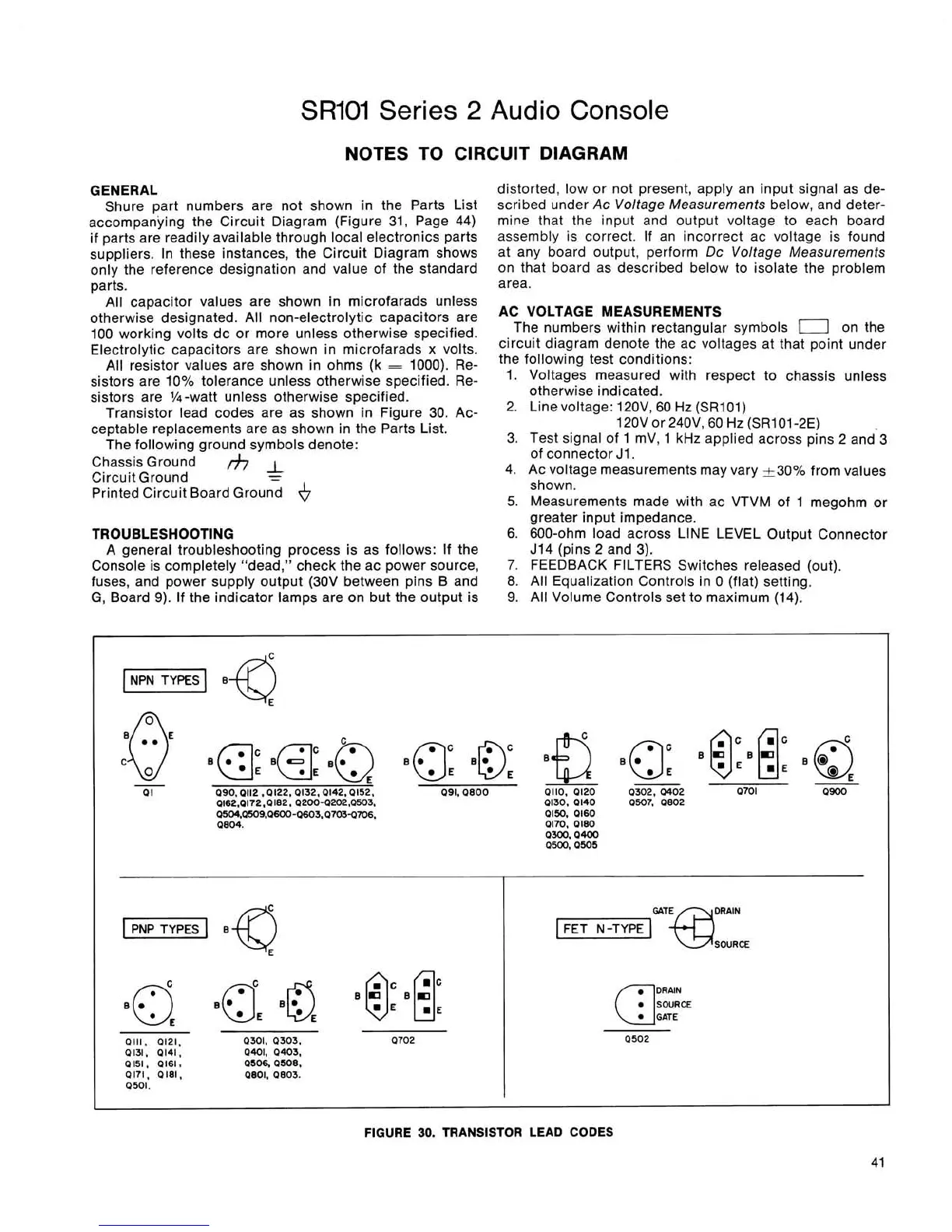
Transistor lead codes are as shown in Figure 30. Ac-
ceptable replacements are as shown in the Parts List.
The following ground symbols denote:
Chassis Ground
Circuit Ground
lfi&
-
Printed Circuit Board Ground
6
AC VOLTAGE MEASUREMENTS
The numbers within rectangular symbols
0
on the
circuit diagram denote the ac voltages at that point under
the following test conditions:
1. Voltages measured with respect to chassis unless
otherwise indicated.
2.
Line voltage: 120V, 60 Hz (SRIO1)
120V or 240V,
60
Hz
(SRI 01
-2E)
3. Test signal of 1 mV, 1
kHz
applied across pins
2
and'3
of connector J1.
4. Ac voltage measurements may vary 230% from values
shown.
5.
Measurements made with ac VTVM of 1 meaohm or
-
greater input impedance.
TROUBLESHOOTING
6.
600-ohm load across LINE LEVEL Output Connector
A general troubleshooting process is as follows: If the J14 (pins
2
and 3).
Console is completely "dead," check the ac power source,
7.
FEEDBACK FILTERS Switches released (out).
fuses, and power supply output (30V between pins B and
8.
All Equalization Controls in 0 (flat) setting.
G, Board 9). If the indicator lamps are on but the output is
9. All Volume Controls set to
maximum (14).
~lIWR~IN
SOURCE
FIGURE
30.
TRANSISTOR LEAD CODES
 Loading...