A common practice when adding a mixer in this manner
is to connect similar-use microphones (for instance, all
drum, string or horn microphones) to a single mixer which
is fed into the Console. The Console individual channel
Volume Control (1) then controls an entire section, fa-
cilitating adjustment of that section during a performance.
With this set-up, set the channel INPUT
ATTEN (14) to 0 and
adjust the mixer volume controls in the mid-to-high range;
adjust the mixer master volume control as required to keep
the Console volume control in the desirable middle range.
The
M68FC mixer has a switch-selectable low- or high-
impedance microphone output. When using an M68FC-type
mixer into a Console MIC LEVEL lnput Jack (33), set the
mixer MIC OUT switch to low impedance, and make neces-
sary adjustments as described above. It is sometimes de-
sirable to use the auxiliary output from the mixer into the
Console channel 7 (or 8) AUX. INPUT Jacks (32) if the mixer
output is derived from a source which is not required con-
stantly (such as an orchestra); the same channel
7
(or 8)
MIC LEVEL lnput Jack can be used as a regular microphone
input, with the front-panel AUX-MIC Switch (14) selecting
one or the other for the program. (Refer to lnput Channels,
Page 5, for a description of the AUX-MIC Switch function.)
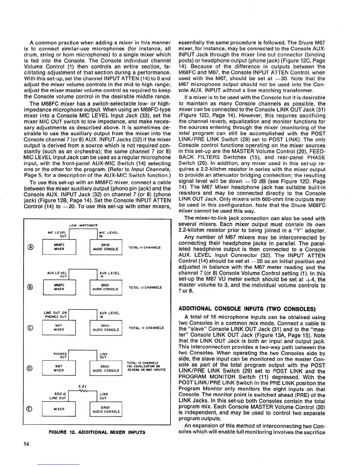
To use this set-up with an
M68FC mixer, connect a cable
between the mixer auxiliary output (phono pin jack) and the
Console AUX. INPUT Jack (32) on channel 7 (or 8) (phone
jack) (Figure
128, Page 14). Set the Console INPUT ATTEN
Control (14) to -20. To use this set-up with other mixers,
LOW IMPEDANCE
MIC LEVEL MIC LEVEL
AUX LEVEL AUX LEVEL
MlXER
LINE OUT OR AUX LEVEL
PHONES OUT
0
MIXER
PHONES
TOTAL:
I2
CHANNELS
SRlOl
IN0
EQUALIZATION OR
MIXER
REVERB
ON
~67 INPUTS)
I
600n
;IP;
,
LINE OUT
MIXER
SRlOl
AUDIO CONSOLE
FIGURE
12.
ADDITIONAL MIXER INPUTS
essenfially the same procedure is followed. The Shure M67
mixer, for instance, may be connected to the Console AUX:
INPUT Jack through the mixer line out connector (binding
posts) or headphone output (phone jack) (Figure
12C, Page
14). Because of the difference in outputs between 'the
M68FC and M67, the Console INPUT ATTEN Control, when
used with the M67, should be set at -30. Note that the
M67 microphone output should not be used into the Con-
sole AUX. INPUT without a line matching transformer.
If a mixer is to be used with the Console but it is desirable
to maintain as many Console channels as possible, the
mixer can be connected to the Console LlNK OUT Jack (31)
(Figure
12D, Page 14). However, this requires sacrificing
the channel reverb, equalization and monitor functions for
the sources entering through the mixer (monitoring of the
total program can still be accomplished with the POST
LINKIPRE LlNK Switch (29) set to POST LINK). The only
Console control functions operating on the mixer sources
in this set-up are the MASTER Volume Control
(20), FEED-
BACK FILTERS Switches
(15), and rear-panel PHASE
Switch (26). In addition, any mixer used in this set-up re-
quires a 2.2-kilohm resistor in series with the mixer output
to provide an attenuator bridging connection; the resulting
signal level will be down -10 dB (see Figure
12D, Page
14). The M67 Mixer headphone jack has suitable built-in
resistors and may be connected directly to the Console
LlNK OUT Jack. Only mixers with 600-ohm line outputs may
be used in this configuration. Note that the Shure
M68FC
mixer cannot be used this way.
The mixer-to-link jack connection can also be used with
several mixers. Each mixer output must contain its own
2.2-kilohm resistor prior to being joined in a
"Y"
adapter.
Any number of M67 mixers may be interconnected by
connecting their headphone jacks in parallel. The paral-
leled headphone output is then connected to a Console
AUX. LEVEL lnput Connector (32). The INPUT
ATTEN
Control (14) should be set at -20 as an initial position and
adjusted in balance with the M67 meter reading and the
channel 7 (or 8) Console Volume Control setting (1). In this
set-up the M67 VU meter switch should be set at +4, the
master volume to 3, and the individual volume controls to
7 or
8.
ADDITIONAL CONSOLE INPUTS (TWO CONSOLES)
A total of 16 microphone inputs can be obtained using
two Consoles in a common mix mode. Connect a cable to
the "slave" Console LlNK OUT Jack (31) and to the "mas-
ter" Console LlNK OUT Jack (Figure
13A, Page 15). Note
that the LlNK OUT Jack is both an input and output jack.
This interconnection provides a two-way path between the
two Consoles. When operating the two Consoles side by
side, the slave input can be monitored on the master Con-
sole as part of the total program output with the POST
LINK/PRE LlNK Switch (29) set to POST LlNK and the
PROGRAM MONITOR Switch (11) depressed. With the
POST LINKIPRE LlNK Switch in the PRE LlNK position the
Program Monitor only monitors the eight inputs on that
Console. The monitor point is switched ahead (PRE) of the
LlNK Jacks. In this set-up both Consoles contain the total
program mix. Each Console MASTER Volume Control (20)
is independent, and may be used to control two separate
program outputs.
An expansion of this method of interconnecting two Con-
soles which will enable full monitoring involves the sacrifice
 Loading...