10. Reverb circuit measurements made with REVERB IN-
TENSITY Controls full clockwise, and Master Reverb
Switch depressed (on). Note that reverb spring and
following stages vary with frequency; measurements
given are typical only.
11. Monitor circuit measurements made with all MON-
ITOR Switches depressed (on), and PROGRAM MON-
ITOR Switch released (off).
12. Tone oscillator circuit measurements on Program Out-
put (Bd.
5)
made with TONE OSC LEVEL Switch on.
DC VOLTAGE MEASUREMENTS
The numbers within elliptical symbols
o
on the
circuit diagram denote the dc voltages at that point under
the following test conditions:
1.
Voltages measured with respect to chassis unless
otherwise indicated.
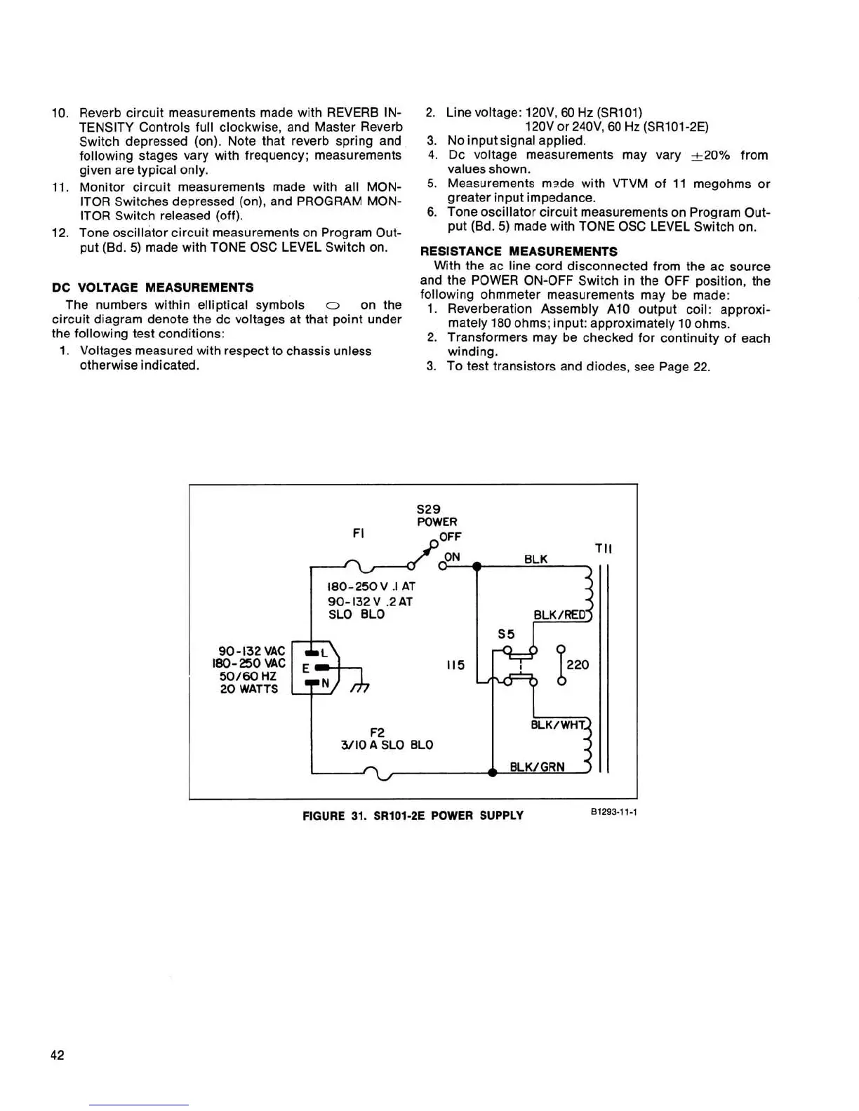
2. Line voltage:
120V, 60
Hz
(SR101)
120V or 240V, 60
Hz
(SR101-2E)
3.
No input signal applied.
4. Dc voltage measurements may vary
*20% from
values shown.
5.
Measurements msde with VTVM of 11 megohms or
greater input impedance.
6.
Tone oscillator circuit measurements on Program Out-
put
(Bd.
5)
made with TONE OSC LEVEL Switch on.
RESISTANCE MEASUREMENTS
With the ac line cord disconnected from the ac source
and the POWER ON-OFF Switch in the OFF position, the
following ohmmeter measurements may be made:
1. Reverberation Assembly A10 output coil: approxi-
mately 180 ohms; input: approximately 10 ohms.
2. Transformers may be checked for continuity of each
winding.
3.
To test transistors and diodes, see Page 22.
S29
POWER
TI1
BLK
180-250
V
.I
AT
90- 132
V
.2
AT
SLO
BLO
11
5
F2
3/10
A
SLO BLO
i
BLKfGRN
-
FIGURE
31.
SRlO1-2E POWER SUPPLY
81293-1
1-1
 Loading...